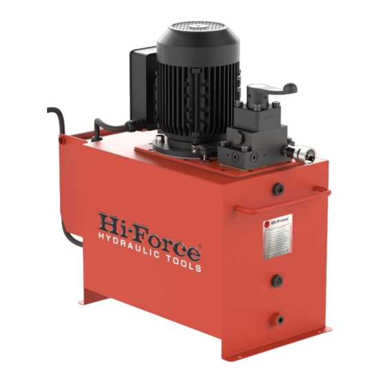
Hi-Force HEP5 Kullanım Kılavuzu - Sayfa 7
Su Pompası Hi-Force HEP5 için çevrimiçi göz atın veya pdf Kullanım Kılavuzu indirin. Hi-Force HEP5 8 sayfaları. Electric driven pump
Ayrıca Hi-Force HEP5 için: Kullanım Talimatları Kılavuzu (19 sayfalar)

PREPARING THE PUMP FOR FIRST USE
1. Immediately after unpacking, examine
the pump for signs of transit damage and
if found contact the shipping company.
2. Establish the oil level in the oil reservoir
using the level gauge on the end of the
tank. Depending on the shipping method
used, the reservoir may either be supplied
full or empty. If the reservoir is empty it
must be correctly filled before use.
Remove the temporary transit plate which
is fitted in the position of the filler breather
cap (5) by undoing the 3 screws. Fit the
filler breather cap (packed separately)
using the 3 screws which held the transit
plate.
3. To fill the reservoir: Remove the filler cap
(5) and fill the tank with clean HFO46 oil to
the upper level indicator (7).
4. Make sure that the voltage indicated on
the motor rating plate corresponds with
the available supply.
5. Remove steel or plastic hexagon
headed plugs and make hydraulic
connections to service ports (11). These
ports have a 3/8" NPT female thread and
the corresponding male connections
should be wrapped with PTFE tape or
other suitable sealant. N.B On 3 way valves
the service port is the right hand one,
when viewed as in figure 1.
6. Ensure the lever of the hydraulic
directional control valve (2) is in the
neutral position: This is fully anticlockwise
for models with 2 way valve or the central
position for models with 3 or 4 way valves.
Where valves are remotely mounted,
ensure these are adjusted such that
pressure will not build up during the
starting operation. See table on page 1.
7. Ensure switch is set to 'off' (8). Connect
motor to required power source.
Hi-Force Limited – Prospect Way – Daventry – Northants NN11 8PL – United Kingdom
Tel: +44(0) 1327 301000: Fax: +44(0) 1327 706555: Website: www.hi-force.com
INSTRUCTION MANUAL – Electric Driven Pump Series HEP:
Model Series: HEP1, HEP103, HEP2, HEP3, HEP5
8. Check the direction of the motor
rotation by turning the starter switch (8) to
the 'ON' position then to the 'off' position,
whilst doing this observe the motor fan.
The motor should run in a clockwise
direction viewed from above. If the
direction is wrong check the wiring of the
electrical connector. Running the pump
with incorrect rotation may damage the
low pressure pump unit.
OPERATION OF PUMPS WITH MANUAL
VALVES
Hi-Force does not necessarily know what
equipment this pump will power. Read
and understand the appropriate
operating instructions relating to the
equipment in use.
1. With all hydraulic connections made
and motor running, operate the
directional control valve (2) if fitted to
control the cylinders or tools in use.
For pumps with 2 way valves: Turning the
lever fully clockwise will supply oil to the
service port and advance the cylinder.
Turning the lever anticlockwise will retract
the cylinder.
For pumps with 3 way valves: Mid position
is the load hold position. Moving the lever
so that it is above the service port (anti-
clockwise) will supply oil to the port and
advance the cylinder. Moving the lever
away from the service port will connect
the service port to tank and retract the
cylinder.
For pumps with 4 way valves: Mid position
is the load hold position. Moving the lever
so that it is above either service port will
supply oil to that port and connect the
opposite port to tank.
2. The pump is fitted with an adjustable
pressure relief valve (10) to restrict the
output pressure to any desired value up to
the maximum working pressure of the
pump. To increase the relief valve setting
