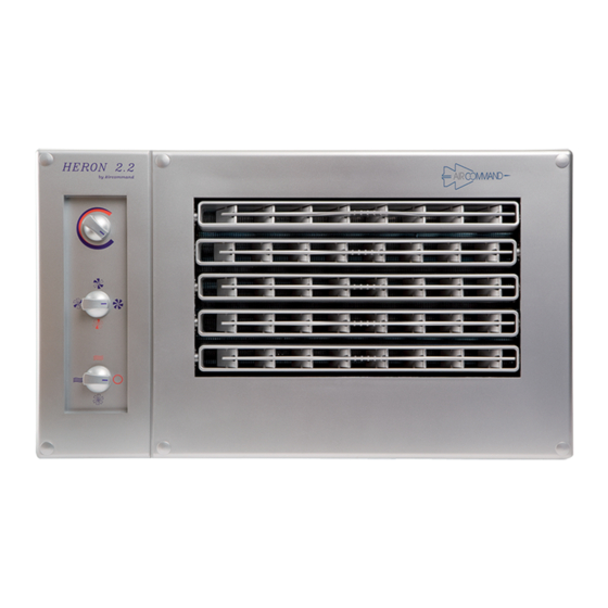
Aircommand HERON 2.2 Kullanıcı El Kitabı - Sayfa 9
Klima Aircommand HERON 2.2 için çevrimiçi göz atın veya pdf Kullanıcı El Kitabı indirin. Aircommand HERON 2.2 17 sayfaları.
Ayrıca Aircommand HERON 2.2 için: Kurulum Talimatları Kılavuzu (10 sayfalar)

POWER SUPPLY
The unit is designed to plug into a normal mains electricity supply.
This plug must be accessible after installation. If a new plug is installed, then it
must be positioned near to the airhandler and be easily accessible.
Note: The supply cord is designated Type F. If replacement is necessary it should be
replaced by an Aircommand approved technician.
Tips on Making Flare Joints
■
1. Always use a proper Tube Cutter to cut tube to length (Never Ever a
Hacksaw).
2. Remember to put the flare nut on the tube prior to making flare.
3. Always deburr the inside of the tube. Buy a proper deburring tool to do this. It
is a good idea to wipe around the inside of the tube to wipe away any copper
particles that may have come off during deburring.
NB. If an inside burr is left on, the flaring head will inevitably drive this burr onto the
surface of the flare, resulting in a pitted flare face, which will almost certainly
leak.
4. Clamp the tube in the flaring block firmly. For 1/4" tube (6.4Ø), the unflared
tube should protrude 1.0 mm. For 3/8" tube (9.5Ø) the unflared tube should
protrude 1.5 mm. See Fig. I, J & K
5. The flaring head should be lubricated with a smear of oil. (Preferably vacuum
pump oil).
Tighten down flaring head by:
a) Contact tube with flare head
b) Advance 3/4 turn
c) Back off 1/4 turn
This oscillating manner will ensure an accurate contour and guard against
splitting.
6. Check that the resulting flare shows a bright continuous ring around the face,
and no imperfections exist.
CHARGING THE SYSTEM
The system is charged with R22 or R407C as marked in Austrualia / New
Zealand or R407C in Europe, which is a prescribed refrigerant gas. Most
states / countries will require the installer to have an appropriate license.
The condenser set is factory precharged, but the Air handler and connecting
pipework needs to be evacuated of noncondensables.
Please note: In Australia, state/country laws re the handling of prescribed
refrigerants may prohibit the purging method. Such laws take precedence.
Method
• Use a vacuum pump to remove noncondensables from A/H & pipework.
• Tighten all flare nut connections on both the Con/set and the A/H.
• Remove schrader valve caps and connect manifold gauge hoses, preferably to both valves (make sure
valve depressors are set ok).
• If both hoses are fitted, then evacuate for 10 minutes.
• If only one, then evacuate for 15 mins.
• Check that the pump maintains a high vacuum by isolating systems with manifold gauge taps and
observing suction gauge.
• Remove both stem caps, then isolate the vac. pump, before turning on both valve stems. Fully
backseat both, and refit caps.
• Now check for leaks.
d) Advance 3/4 turn etc, until flare
has bottomed in the anvil (don't
tighten on the bottom).
6
Figure I: Prefered flaring
tool ratchet/eccentric type
For 6.4¯ Tube,
1/3 H = 1 mm
For 9.5¯ Tube,
1/3 H = 1.5 mm
1
H
H
3
Figure J
FLARED FITTINGS
A
A. Correctly made flare
B
B. Flare too small
C
C. Flare too large
D
D. Flare is uneven
E
E. Flare has burrs on edge
Figure K
