Hi-Link HLK-LD015-5G Kullanıcı Kılavuzu - Sayfa 4
Kontrol Ünitesi Hi-Link HLK-LD015-5G için çevrimiçi göz atın veya pdf Kullanıcı Kılavuzu indirin. Hi-Link HLK-LD015-5G 8 sayfaları. Radar module
3. Input and Output Interface
The module reserves 5 pin holes with a PIN distance of 1.2mm. The three PINs VCC, GND
and OUT are used by default. If parameters such as distance and delay time need to be modified,
they can be flexibly configured through the serial port RX and TX. When there is no host computer,
RX and TX can also be used as I/O ports to adjust parameters. The following table shows the
definition of each PIN
Pin Name
VCC
Module Power Supply
GND
Ground PIN
OUT
Output Signal
TX
Serial port/burn tDio/IO
RX
Serial port/burn tClk/IO
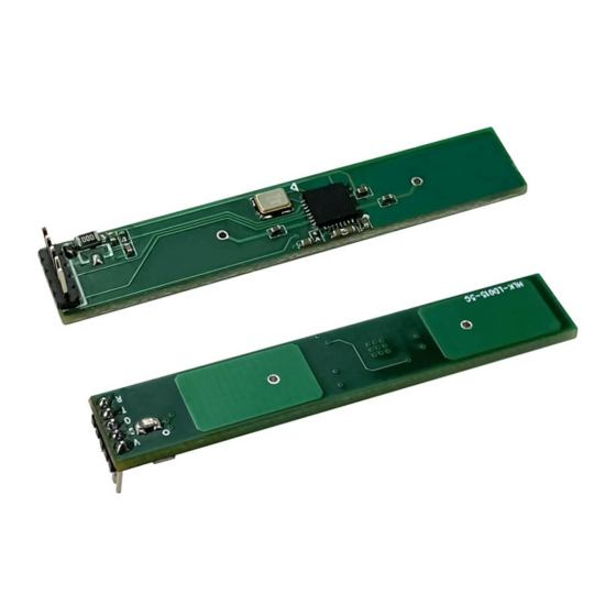
4. Mechanical Dimensions
The figure 2 below is a schematic diagram of the module's size and pin position. The module
length and width are 46mm*8mm. There are no pins and the overall thickness is 2.5mm by default.
If you need pins, the default pin height is 12mm.
HLK-LD015-5G
Function
with LDO attached, VCC is 7~12V, the default power consumption
of the module is 35mA, and the recommended power drive
The default output 5V high and low level, can be modified to PWM
Can be used for software upgrade or performance parameter
Can be used for software upgrade or performance parameter
The default LDO is not attached, VCC is 5V, and the version
capability is over 50mA
output as needed
Unit: mm
Figure 2
Page 2 / 6
Remarks
User Manual