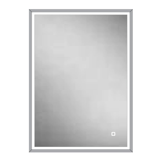
HiB 47900 Manuel
İç Mekan Mobilyaları HiB 47900 için çevrimiçi göz atın veya pdf Manuel indirin. HiB 47900 2 sayfaları. Cabinets
Ayrıca HiB 47900 için: Talimatlar Kılavuzu (9 sayfalar)

This product is suitable for installation in zones:
&
2
Outside Zone
All installations must comply with guidelines which are based on a zonal
concept. The diagram above illustrates this concept and must be followed
to ensure the safe installation of electrical appliances in the bathroom.
These regulations apply to domestic installations only. Installations must be
made in accordance with the current IEE wiring regulations and relevant
building regulations. HiB recommends that all electrical bathroom
products should only be fitted by a suitably qualified, Part P registered
electrician.
Installation
This product can only be recessed into a wall. Before installation ensure you
take note of the dimensions of the recessed area and the side fixing points
inside the cabinet carcass (See fig. B & E).
is suitable to accommodate for the size and weight of a recessed cabinet.
The cabinet should be placed in a suitable location, (according to the zonal
diagram (Fig. 1) above). Ensure the domestic electrical mains supply
to which the cabinet is to be connected is turned off. Before drilling,
ensure that there are no hidden cables or pipes in the wall.
recommended that the fitting of this product is conducted by two people.
1. Before commencing installation, remove the door(s) from the carcass. This
is done by gently pulling at the tab at the back of each
Place the cabinet door(s) carefully onto a soft surface where they will not
get damaged during installation.
disconnected during transport.
2. Measure the dimension of the cabinet carcass (but not the front aluminium
fascia).
3. Using these dimensions, take a soft pencil and mark the outline for the
required aperture in the wall. Take great care to mark this accurately,
straight and level.
4. Using an appropriate tool, cut or channel out the aperture in the wall
where the cabinet will fit (Fig. B).
5. If it is necessary, install supporting baton(s) or noggin(s) around the
recessed area (see Fig. C) to which the cabinet can be secured. These
supports must be completely vertical and parallel to the cabinet to prevent
the cabinet twisting when fitted.
6. Connect the domestic mains supply according to the wiring diagram (See
Fig. 2) on the back page and manoeuvre the cabinet into the wall aperture
(See Fig. D).
7. Using a suitable screwdriver or drill, secure the cabinet into the wall
aperture with the supplied screws, via the two holes (two on each side) See
Fig. E.
T:
+44 (0)20 8441 0352
F:
+44 (0)20 8441 0219
Building 3, North London Business Park, Oakleigh Road South, New Southgate, London. N11 1GN
©HiB Copyright: No part of this document may be reprinted or duplicated without HiB consent. All sizes and measurements are approximate, but we do try and make sure they are as accurate as possible. In the
interest of continuous product development, HiB reserves the right to alter specifications as necessary. E & OE.
(Fig. 1)
Ensure the construction of the wall
It is strongly
hinge, as per Fig. A.
The door(s) have been intentionally left
E:
Thank you for purchasing this HiB product.
Please read through these instructions carefully and refer back to them
during installation to ensure that your product is fitted safely and that it
retains its high quality finish.
Please retain this leaflet for future reference.
8. Insert the supplied shelf brackets into the appropriate holes on the inside
of the cabinet, depending on what height each shelf is required. Slide each
shelf into position and secure in place by tightening the small plastic grub
screw on the underside of each shelf bracket.
9. With help from a second person, offer the door up to the cabinet and
carefully connect the wires using the connection blocks - take care to
connect the blocks in the correct orientation, so that the red wire connects
to the red wire and black to black. Once connected, carefully slide any
excess wiring and the connector blocks inside the carcass and reconnect
the hinges. Hinges are reconnected by clipping the front of the hinge in
and then applying pressure on the back of the hinge until an audible 'click'
is heard.
10. If necessary, hinges can be adjusted to reposition the door(s) see Fig. G.
11. Switch mains supply back on.
Door Removal (Fig. A)
(Fig. B)
(Fig. D)
(Fig. E)
hib.co.uk
FI#02 015 R170201
Vanquish Cabinets
Vanquish 50
Art No. 47600
Vanquish 60
Art No. 47700
Vanquish 80
Art No. 47800
Vanquish 120
Art No. 47900
(Fig. C)
(Fig. F)
Ver No.
1.0 Jan 2017
