CEL-MAR ADA-1021 Kullanıcı Kılavuzu - Sayfa 5
Medya Dönüştürücü CEL-MAR ADA-1021 için çevrimiçi göz atın veya pdf Kullanıcı Kılavuzu indirin. CEL-MAR ADA-1021 12 sayfaları. Rs-232 to current loop converter
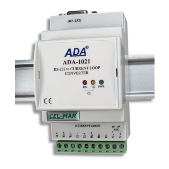
ADA-1021
The receiver has signalization of non current flow through optocoupler. It is indicated by the red LED RX on front panel of the
converter. This LED lit when it is:
- not connect transmitter to receiver,
- wrong connection of transmitter to receiver,
- broken connection of transmitter to receiver.
The diagram is shown on figure below.
I1 +
I= 0 / 20mA
I
I1 -
I1 – Transmitter's
Current source
2.5. ISOLATION
Converter ADA-1021 has 3-way galvanic isolation on level 1kV= or 3kV=, depend on version described in section VERSIONS.
3. INSTALACJA
This chapter will show how to connect ADA-1021 to PC, Current Loop bus, RS232 bus and power supply and how to use it.
In the purpose of minimization of disruptions from environment is being recommended to:
● apply multipair type shielded cables, which shield can be connected to the earthing on one end of the cable,
● arrange signal cables in the distance not shorter than 25 cm from powering cables,
● apply cable of adequate cross-section due to voltage drops for converter powering,
● use Interference suppression filters for power supply converters that are installed within a single object.
● not supply converter from power circuit device that generates large impulse interference such as transmitters, contactors,
3.1. ASSEMBLING
The ADA-1021 enclosure is adapted to assembly on TS-35 (DIN35) rail. To instal converter should the upper part of casing hang
hooks on the rail, than push the lower part until to hearing characteristic "Click" sound.
3.2. CONNECTION OF DEVICES WITH RS232 PORT
TX+
I= 0 / 20mA
TX-
Passive Transmitter
Fig. 2. Diagram of the transmitter & receiver ADA-1021 Current Loop
3-WAY ISOLATION
RS232
Fig. 3. Isolation structure
Not use RI 9
Not use RTS 8
Not use CTS 7
Not use DTR 6
The Signals looped on the converter :
1. DTR – DSR – DCD
2. RTS - CTS
Fig. 4. RS232 interface signals of DB-9F (female) connector
I2 +
I= 0 / 20mA
I2 -
I2 – Receiver's
Current source
Current Loop
Power Supply
10 - 30VDC
5 GND
4 DSR not use
3 RX
2 TX
1 DCD not use
5
RX+
I
RX-
Passive Receiver