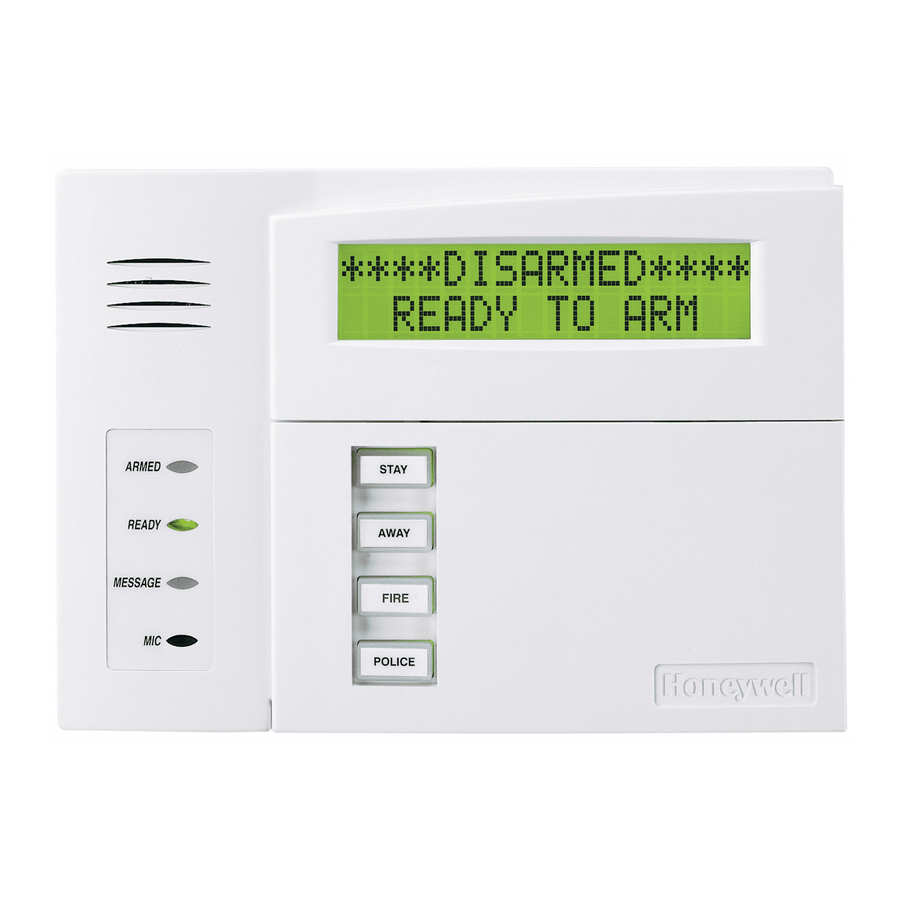
ADEMCO Vista-10P Programlama Kılavuzu - Sayfa 10
Güvenlik Sistemi ADEMCO Vista-10P için çevrimiçi göz atın veya pdf Programlama Kılavuzu indirin. ADEMCO Vista-10P 17 sayfaları. Alarm control panel

*57 FUNCTION KEY PROGRAMMING
Option
Function
01
Paging
02
Time Display
03
Arm AWAY
04
Arm STAY
05
Arm NIGHT-STAY
06
Step Arming
07
Device Activation
08
Comm. Test
09
Macro Key
00
Emergency Keys:
Personal Emergency
Silent Alarm
Audible Alarm
Fire
Emergency Keys:
Start Function Key Programming mode by pressing ∗ 57 while in Data Programming mode.
Press Key to Pgm
0 = Q u i t
0
Key "A" Func
Zone 95
00
OUTPUT RELAYS WORKSHEET FOR ∗79, ∗80 and ∗81 (
∗79 RELAY MAPPING (Must program before using *80)
Start Output Device Mapping by pressing *79 while in Data Programming Mode.
ENTER OUTPUT NO.
00 = QUIT
xx
17 OUT NORM LOW
0 = NO 1 = YES
0
XX OUTPUT TYPE
DELETE?
0
XX MODULE ADDR
07-15
yy
XX REL POSITION
1-4
zz
A
B
C
zone 95
zone 99
zone 96
A = paired keys [1] / [∗] (zone 95); B = paired keys [∗] / [#] (zone 99); C = paired keys [3] / [#] (zone 96)
Press the desired function key, A-D.
NOTE: A key programmed as a function key is no longer available to be used as an end-user macro key or
panic key.
[∗] to continue
Enter the desired function for this key:
00 =
For the Function key selected, the function will be as follows (system default):
If A selected = Zone 95 (emergency key, same as [1] [∗] pair)
If B selected = Zone 99 (emergency key, same as [∗] [#] pair)
If C selected = Zone 96 (emergency key, same as [3] [#] pair)
If D selected = Single-button paging
01 =
Single-button paging (sends a 999-9999 message to pager)
02 =
Display time
03 =
Arm AWAY (reports as User 00 if closing reports are enabled)
04 =
Arm STAY (reports as User 00 if closing reports are enabled)
05 =
Arm NIGHT-STAY (reports as User 00 if closing reports enabled)
06 =
Step Arming (arms STAY, then NIGHT-STAY, then AWAY)
07 =
Output Device Command (for device programmed as system operation type 66 in *80 Menu Mode)
08 =
Communication Test (sends Contact ID code 601)
09=
Macro Key (defined by [#] [6] [6] command)
[∗] to continue; returns to key number prompt with the next function key letter displayed.
Output No. Module Addr. Pos (1-4) Description
01
12
02
12
03
12
12
04
On-Board Trigger 1: Norm output =
17
18
On-Board Trigger 2: Norm output =
Enter the logical (or reference) relay number as used in the system.
01-04 = relays; 17-18 = on-board triggers (can be programmed for inverted output; see next prompt)
[∗] to continue
This prompt appears only for triggers 17 and 18.
0 = no (standard default); sets the trigger output level normally high
1 = yes; sets the trigger output normally low (can be used for resetting 4-wire smoke detectors by
connecting trigger wire to the negative power terminal of the smoke detector, selecting 1 at this prompt,
and setting as zone type 54, fire zone reset, in *80 Menu mode)
[∗] to return to Output Number prompt
Enable or delete this output.
0 = delete this output number; 1 = enable output
[∗] to continue
Enter the module's predefined address "12" (set the module's DIP switches to "12").
[∗] to continue
Enter the actual (or physical) relay number, 1-4, with respect to the Relay Module upon which it is located.
[∗] to return to the Output Number prompt for programming the next device
D
Comments
Device:
paging
n/a
n/a
n/a
n/a
Applicable only if Relays are to be used)
– 10 –
