GAI-Tronics 352-101 Manuel - Sayfa 2
Telefon GAI-Tronics 352-101 için çevrimiçi göz atın veya pdf Manuel indirin. GAI-Tronics 352-101 19 sayfaları. Division 1 smart hazardous area telephones
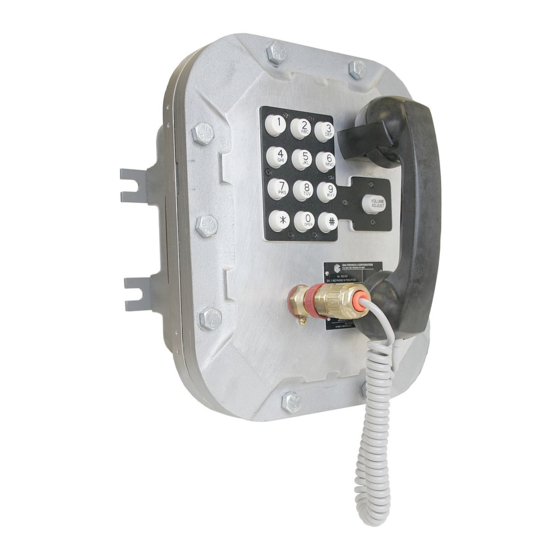
Model 352-101, 352-102, 352-103, & 352-104 Div. 1 SMART Hazardous Area Telephones
The GAI-Tronics SMART Telephone product line provides the flexibility to address a diverse range of
applications. A wide variety of functions can be achieved by altering the configuration data stored in the
telephone's non-volatile memory. These configuration options include:
Call progress detection, control, and call logging
Auto-calling, auto-answering, and auto-dialing facilities
Function inhibiting (e.g. tone pad and manual keypad dialing)
Maximum call duration
These functions are initially programmed during manufacturing and testing. After installation, they can
be programmed remotely via DTMF data call.
All SMART Telephones are line-powered and can be connected to the 24 V dc or 48 V dc analog station
port of Private Branch Exchange (PBX), Private Automatic Branch Exchange (PABX) or KSU.
Connection may not be made to pay telephone extensions or shared service (party) lines.
TMA users can schedule auto-dial maintenance calls to alert maintenance personnel of any unusual sensor
or fault conditions that exist. SMART Telephones can also be programmed to generate an auto-dial
maintenance call when certain sensor events are discovered. Access to the SMART Telephone's
maintenance mode is restricted through the use of the maintenance access PIN. The maintenance access
PIN should be distributed only to trained maintenance personnel.
Installation
Installation Guidelines
These enclosures must be installed by trained, qualified and competent personnel. Installation must
comply with state and national regulations, as well as safety practices for this type of equipment.
CAUTION
Do not install this equipment in hazardous areas other than those indicated
on the approval listing in the "Specifications" section of this manual. Such installation may cause a
safety hazard and consequent injury or property damage.
The mounting location must be flat and provide proper clearance, rigidity and strength to support the
enclosure and all contained devices.
WARNING
Securely fasten the enclosure to the mounting location, using 3/8-inch diameter
steel mounting bolts and washers, or washer head bolts.
WARNING
Do not disconnect equipment while energized.
Insure proper grounding to protective earthing.
WARNING
The front cover is not hinged to the rear enclosure. When the cover bolts are
removed, the cover must be adequately supported.
ATTENTION
accordance with the National Electrical Code or applicable local codes.
f:\standard ioms - current release\42004 instr. manuals\42004-455b.doc
02/13
Installation should be performed by qualified personnel and only in
Pub. 42004-455B
Page 2 of 17