GAI-Tronics 354-701YL Manuel - Sayfa 7
Telefon GAI-Tronics 354-701YL için çevrimiçi göz atın veya pdf Manuel indirin. GAI-Tronics 354-701YL 17 sayfaları. 354-70x series nema 4x voip telephone
NEMA 4X VoIP Telephones
Wiring
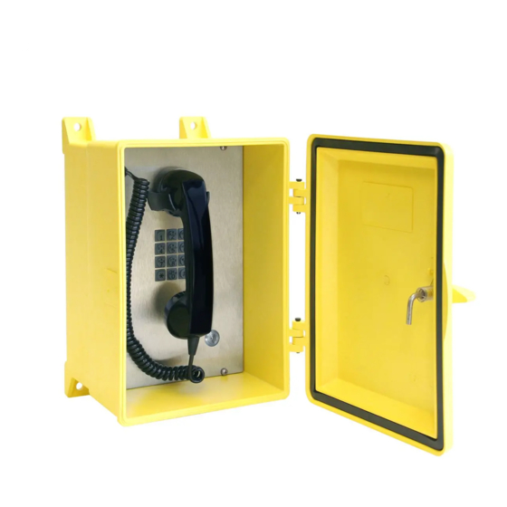
1. Remove the four screws from the front panel and turn it to the right so that the interior surface faces
you. Allow the wiring to remain connected. The front panel can be hung from the front door by
hooking a small piece of wire in the mounting holes of the panel. The front panel interior surface and
the back box interior now face you. Refer to Figure 5. This configuration presents the easiest access
for troubleshooting and setting adjustments.
2. Plug the incoming Cat5 data line to the network RJ45 cable jack on the underside of the VoIP circuit
PCBA. See Figure 6.
Install any additional connections as indicated below. Refer to Figure 5 for wiring details. Refer to Table
4 on Page 9 for the recommended conductor sizes.
Network Cable
Connect a Cat5 or Cat5e UTP cable with an RJ45 connector between the Local Area Network (LAN) and
the VoIP PCBA. See Figure 6.
Power-Over-Ethernet (POE)
Connect power to the system as indicated in your POE equipment manual. (Power Mode A, Class 0)
P:\Standard IOMs - Current Release\42004 Instr. Manuals\42004-520A.docx
03/17
Figure 5. Installation and Maintenance Configuration
Pub. 42004-520A
Page 7 of 15