HID VertX EVO V1000 Kurulum Kılavuzu - Sayfa 6
Kontrolör HID VertX EVO V1000 için çevrimiçi göz atın veya pdf Kurulum Kılavuzu indirin. HID VertX EVO V1000 19 sayfaları.
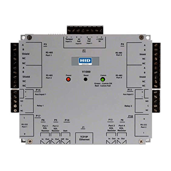
VertX EVO V1000 Installation Guide
1.4
Wiring VertX EVO
Warning: VertX EVO V1000 is a NON-PoE device. DO NOT connect J1 (Ethernet port) to a PoE
capable port. This applies to both direct PoE Power Sourcing Equipment (Endspan PSE) and
PoE injector (Midspan PSE) equipment. Not all PSE's correctly detect Non-PoE-capable
devices, and such PSE's may not function as expected when connected to Non-PoE
equipment.
Installation Note: Carefully peel the attached Warning Label from the bottom of the unit and
leave the label attached to the unit's cover for future reference.
CAUTION: Connectors on the VertX EVO devices are positioned to be mirror images and are not
interchangeable once the installation is complete. Therefore, you cannot unplug a connector from
one side and plug it into the corresponding connector on the other side.
1.
Network Connection: Connect the VertX EVO V1000 to the network using a standard Cat5
network patch cable. Connect one end of the Cat5 network patch cable to the J1 (RJ-45)
connector on the V1000 and the other end to the network connection point (network jack, hub,
switch, or router) on your site.
Note: Two LED lights exist on the RJ-45 connector. The green LED denotes Ethernet Activity
and the yellow LED denotes speed. When the Yellow LED is on, it indicates 100 Mbits per
second. Another LED in-board is a Duplex LED, indicating duplex communications are
available.
2.
Power and Alarm input connections (All VertX EVO units): Connect
power by providing appropriate DC input to the P7 connector.
Appropriate DC input goes to Pin 1 and ground to Pin 2. Batt Fail, AC
Fail, and Tamper switch inputs are wired as shown in the table. Connect
the Bat Fail and AC Fail inputs to battery low/failure and AC failure
contacts provided on the power supply. Connect the Tamper input to a
tamper switch on the enclosure.
3.
RS-485 Connections – The V1000 has
two RS-485 connectors and uses the 10-
pin connector on P3 and P4. Each RS-485
bus can support a maximum of 16 V100-
Series panels using one or two ports.
Having two ports on each bus provides the
option of splitting each RS-485 bus into two
physical connections, allowing a total of four
physical connections for the two busses.
RS-485 busses must be connected in a daisy
chain topology and not a star topology.
The V1000 RS-485 termination jumper
should be in the Out position if there are no
panels attached to the port. If there are
downstream panels attached then the
termination jumper should be in the In
position.
July 2011
© 2003 - 2011 HID Global Corporation. All rights reserved.
Pin #
1
2
3
4
5
6
7
8
PCB
V1000 P3
Pin #
(port 1 and 2)
1
A
2
B
3
Shield
4
Not in use
5
Not in use
6
A
7
B
8
Shield
9
Not in use
10
Not in use
P7
12-24VDC
Ground
Bat Fail -
Bat Fail +
AC Fail -
AC Fail +
Tamper -
Tamper +
PCB
V1000 P4
Pin #
(port 3 and 4)
10
A
9
B
8
Shield
7
Not in use
6
Not in use
5
A
4
B
3
Shield
2
Not in use
1
Not in use
Page 6 of 19