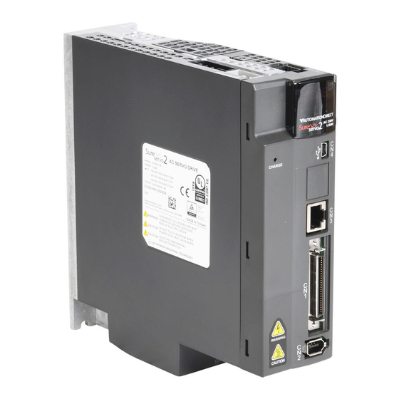
AutomationDirect SureServo2 Hızlı Başlangıç Kılavuzu - Sayfa 3
Kontrolör AutomationDirect SureServo2 için çevrimiçi göz atın veya pdf Hızlı Başlangıç Kılavuzu indirin. AutomationDirect SureServo2 4 sayfaları. 110/220 vac drives
Ayrıca AutomationDirect SureServo2 için: Manuel (18 sayfalar), Hızlı Başlangıç Kılavuzu (2 sayfalar)

(9) Dimensions and weight of servo drive
SV2A-2040 model
SV2A-2075, SV2A-2150 models
180(7.1)
50(2)
70(2.8)
SV2A-2200, SV2A-2300 models
SV2A-2550 model
Weight
0.92 kg (2.02 lb)
SV2A-2750 model
50(2)
36.3(1.43)
5.5(0.22)
M5*0.8
M5*0.8
M ou nti ng
di men si on s
Unit: mm (inch)
Weight
1.3 kg (2.87 lb)
SV2A-2F00 model
Weight
2.7 kg (5.94 lb)
Note: the values displayed in the above figures are measured in metric units. The values displayed in imperial units are
for reference only.
(10) Circuit Protection (maximum allowable values)
Servo drive
Main Voltage Level
model
100-120VAC 1-phase
200-230VAC 1-phase
SV2A-2040
200-230VAC 3-phase
100-120VAC 1-phase
200-230VAC 1-phase
SV2A-2075
200-230VAC 3-phase
100-120VAC 1-phase
200-230VAC 1-phase
SV2A-2150
200-230VAC 3-phase
100-120VAC 1-phase
200-230VAC 1-phase
SV2A-2200
200-230VAC 3-phase
Weight
5.5 kg (12.13 lb)
SV2A-2300
200-230VAC 3-phase
SV2A-2550
200-230VAC 3-phase
SV2A-2750
200-230VAC 3-phase
SV2A-2F00
200-230VAC 3-phase
* Edison JHL fuses
These circuit protection values are the maximum values allowed by UL. See section 3) Wire Selection
for recommended wire and circuit protection values. Always follow all local and national electrical codes
when selecting circuit protection.
Separate fuses/breakers can be used for the control circuit. Install two fuses or a double pole breaker if
the control power will be using two phases of a 3-phase system. Due to inrush, each drive control circuit
should have separate circuit protection (don't supply two drives with one breaker).
Control Power
All models
(11) Quick Start Guide
This section will show how to safely and quickly start up a SureServo2 (SS2) drive. Wiring and starting
up the drive should only be performed by a qualified professional. High voltage levels are in use.
Commissioning is quicker and easier using the drive configuration software SV2-PRO, but the entire
start-up procedure can be accomplished with the keypad (detailed here). For further information and
more complete startup instructions, please download the SureServo2 User Manual (SS2 UM) from
www.automationdirect.com. Be sure to visit
Weight
7.5 kg (16.53 lb)
SureServo2 commissioning, programming, and operation.
Preliminary Wiring
To safely and quickly start up a SureServo2 (SS2) drive, several different types of wiring need to be
verified first. Until this wiring and functionality is verified, it is highly recommended to NOT connect main
incoming power (R,S,T) or connect the load to the motor shaft.
Connect the ground wires to the screws at the bottom of the drive. Connect the incoming
1.
ground to one screw and connect the motor ground to the other screw. (The motor ground
wire is in the motor cable SV2C-Pxxx-xxxx.)
Connect the wiring for L1C and L2C (single phase 100-120VAC or 200-230VAC). This is
2.
control power and should be continuously available (not disconnected with E-stop, etc.).
Connect an appropriate safety circuit to CN10. See the wiring diagram elsewhere in this
3.
document or the SureServo2 User Manual. Although the CN10 connector comes pre-wired
with an STO bypass, it is strongly recommended to wire a safety relay to connect STO_A to
/
STO_A and to connect STO_B to
Connect the motor encoder cable (SV2C-Exxx-xxxx) to the motor and to CN2 of the drive.
4.
Connect the appropriate 24VDC input devices to DI1-DI10. Pay close attention to these
5.
Digital Input (DI) definitions. Their default (out-of-the-box) configurations are listed below.
DI1 = Servo On input (wired normally open)
DI5 = Alarm Reset (wired normally open)
DI6 and DI7 = Overtravel inputs. Inputs are wired normally closed (in a fail-safe manner).
If the application is rotary and has no overtravel inputs, these inputs can be temporarily
Weight
15 kg (33.07 lb)
wired to DC common (0 volts) or disabled thru programming (procedure shown below).
DI8 =Override (temporary Motor Stop input wired normally closed). NOTE: The STO input
(CN10) is separate from the Override (temporary Motor Stop input wired normally closed)
input DI8.
Drive
Circuit
Rated
Fuse
Fuse Class
breaker
Input
3.98 A
10A
15A
4.69 A
2.76 A
10A
10A
7.73 A
20A
20A
8.71 A
Class CC
5.09 A
13A
15A
12.56 A
30A
30A
14.82 A
8.09 A
20A
25A
18.03 A
40A
40A
20.83 A
11.36 A
30A
35A
Class J
14.52 A
35A
50A
Or
High Speed J*
27.06 A
60A
70A
37.33 A
70A
80A
69.95 A
120A
125A
Circuit breaker
Class CC Fuse
5A
6A
www.automationdirect.com/videos
for helpful videos covering
/
STO_B.
