dbx 263A Kullanım Kılavuzu - Sayfa 4
Kayıt Ekipmanları dbx 263A için çevrimiçi göz atın veya pdf Kullanım Kılavuzu indirin. dbx 263A 8 sayfaları. De-esser

MODEL 263A
CONNECTING THE 263A TO YOUR SYSTEM
The 263A can be used with any line-level device. Some common examples include mixing consoles,
electronic musical instruments, patch bays, and signal processors.
For all connections, refer to the following steps:
1. Turn Off all equipment before making any connections.
2. Mount the 263A in a 1U rack space (optional).
Note: Avoid over-tightening of rackmounting screws as this could damage the front panel.
The 263A requires one rack space (height) and 1/2 rack space (width). It can be mounted above or below
anything that doesnÕt generate excessive heat, since it requires no special ventilation. Ambient tempera-
tures should not exceed 113¼F (45¼C) when equipment is powered. Hardware for mounting your 263A is
provided in the optional accessory kit.
Make connections via 1/4Ó phone jacks according to your requirements.
To save rack space, two 263A units may be mounted side-by-side. In addition, the 263A can be mounted
next to other dbx Òhalf-rackÓ units: 760X Mic Preamplifier, 1024 Buffer Amplifier, 140X Type II Noise,
163A Compressor/Limiter, 363X Dual Noise Gate, 463X OverEasy Noise Gate, or 563X Hiss Reducer.
Hardware for side-by-side mounting is included in the optional accessory kit. If the rubber feet were used
for table top operation, they should be removed at this time.
Caution: Never remove the cover. There are no user-serviceable parts inside, and you run the risk of an
electric shock.
Connect the AC plug (shipped with the unit) to the 263AÕs rear panel POWER jack.
Note: Check the line voltage (printed on the rear panel) and verify that it is correct.
OPERATION MANUAL
Basic Connection
Mounting the 263A in a 1U Rack Space
OPERATION MANUAL
To install a single 263A (left or right side)
HIGH
FREQUENCY
-20 -18 -16 -14 -12 -10
-8
-6
-4
-3
-2
-1
2.5k
Hi-Z MIC
INPUT
BROADBAND
GAIN REDUCTION
1.8k
4k
263A
MORE
800Hz
8kHz
FREQUENCY
DE-ESSER
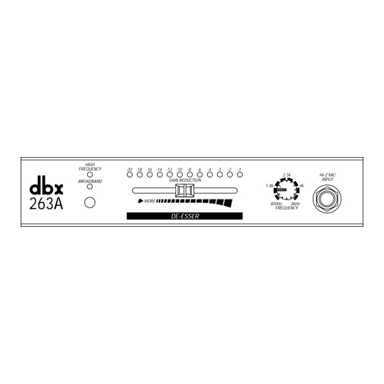
Figure 3: Rack Mounting One 263A Unit
You will need:
1
blank black panel
1
rack ear
1
blank panel adapter piece
1
3/32Ó Allen wrench
1
Phillips screwdriver (not included)
4
pan head Phillips screws
2
hex head screws
NOTE: The optional 263A Accessory Kit includes the tools and hardware listed above, except as noted.
A. Use a Phillips screwdriver to loosely attach the single rack ear to either side of the 263A with
two pan head Phillips screws.
NOTE: If this is the first time the rack ear has been installed, you will be cutting threads
as you drive the screws. This is normal.
B. Loosely attach the adapter piece to the other side of the 263A using two more pan head
Phillips screws and a Phillips screwdriver. See note above.
C. Loosely attach the blank panel and adapter piece using an Allen wrench and two hex head
screws.
D. Align everything on a flat surface and tighten the screws with a Phillips screwdriver and the
hex wrench.
¨
PROFESSIONAL PRODUCTS
