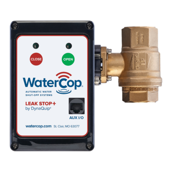
DynaQuip WaterCop LEAK STOP+ Kullanım Kılavuzu ve Kurulum Kılavuzu - Sayfa 10
Kontrol Ünitesi DynaQuip WaterCop LEAK STOP+ için çevrimiçi göz atın veya pdf Kullanım Kılavuzu ve Kurulum Kılavuzu indirin. DynaQuip WaterCop LEAK STOP+ 13 sayfaları.

Troubleshooting
Flood sensor does not detect water.
1. Verify the Leak Stop + is receiving power.
2. Verify the gold prongs are making continued and direct contact with water.
3. If testing, verify tap water is being used rather than distilled or RO water.
Leak Stop + RED or GREEN light does not illuminate
Verify the Leak Stop + is plugged into a grounded 120VAC household outlet and that
outlet is powered.
Leak Stop + motor does not close or open the valve correctly.
1. Verify the Leak Stop + is plugged into a grounded 120VAC household outlet and
that outlet is powered.
2. Verify the valve is correctly orientated to the control box. See page 6 (Installation
Guidelines No. 4).
3. If the brass valve has a solder connection, verify that the ball valve seats were not
damaged by excessive heat.
A. Remove the Leak Stop + control box (retain the spring clip for later re-attachment).
B. Using a fl at-headed screwdriver, gently but fi rmly turn the ball valve stem open
and closed to move the ball. The fl at-headed screw driver will fi t into the slot
of the ball stem and you will be able to move the position of the valve manually.
C. Verify that the ball inside the ball valve can move. The ball will not be completely
loose, but you will be able to rotate it with slightly moderate pressure.
D. Return the ball stem back to the original position so that it will line up with the
drive of the actuator. The stem slot should be perpendicular to the length of the
valve and in-line with the pipe.
4. If the brass valve has a compression fi tting connection, verify the compression fi ttings
were not over tightened causing damage to the valve, seal or seat.
A. Remove the Leak Stop + control box (retain the spring clip for later re-attachment).
B. Using a fl at-headed screwdriver, gently but fi rmly turn the ball valve stem open
and closed to move the ball. The fl at-headed screw driver will fi t into the slot
of the ball stem and you will be able to move the position of the valve manually.
C. Verify that the ball inside the ball valve can move. The ball will not be completely
loose, but you will be able to rotate it with slightly moderate pressure.
D. Return the ball stem back to the original position so that it will line up with the
drive of the actuator. The stem slot should be perpendicular to the length of the
valve and in-line with the pipe.
5. If the valve does not complete the rotation due to blockage in the valve, the unit will
go into the ALARM state. Both lights will fl ash, alarm will sound and the alarm relay
will activate. To silence the alarm, press one of the buttons on the face of the actuator.
Refer to Troubleshooting section 4 for valve troubleshooting.
10
