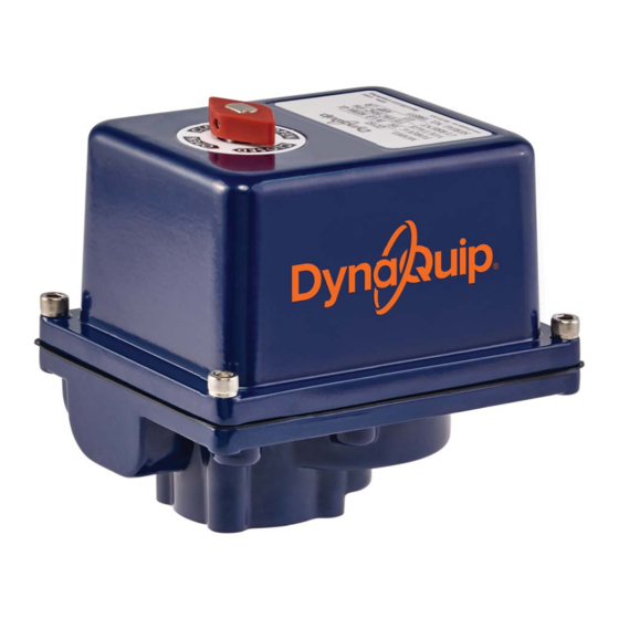
DynaQuip EYSA Series Kurulum, Bakım ve İşletme Kılavuzu - Sayfa 2
Kontrolör DynaQuip EYSA Series için çevrimiçi göz atın veya pdf Kurulum, Bakım ve İşletme Kılavuzu indirin. DynaQuip EYSA Series 12 sayfaları.

Please read and save these instructions. Read carefully before attempting to assemble, install, operate or maintain
the product described. Protect yourself and others by observing all safety information. Failure to comply with
instructions could result in personal injury and/or property damage! Retain instructions for future reference.
Features
•
Actuators can be mounted in any position
•
Actuators can be wired in parallel
•
Output shaft rotates clockwise to close and
counterclockwise to open
•
Type 316 stainless steel output shaft
•
Thermo overload protection to guard motor
against overheating
WARNING:
POWER UNLESS UNIT IS FULLY
ASSEMBLED AND MOUNTED.
ALWAYS DISCONNECT ELECTRIC POWER SOURCE
AND RELIEVE PRESSURE IN THE SYSTEM PRIOR TO
MAINTENANCE. IT IS RECOMMENDED THAT EYE
PROTECTION BE WORN WHILE SERVICING
THE SYSTEM.
FAILURE TO COMPLY WITH ABOVE WARNINGS
COULD RESULT IN PERSONAL INJURY AND/OR
DAMAGE TO THIS PRODUCT.
Inspection Upon Receipt
1. Visually inspect to be sure actuator has not been
damaged in transit.
2. Verify that Model Number is correct as ordered.
3. Verify that electrical supply voltage is the same as
specified on the actuator label.
4. Verify that NEMA rating on label is as required:
Weatherproof/Corrosion Resistant (NEMA 4, 4X).
5. Check that mounting bolt pattern and output shaft
adapter configurations are as required.
Installation
1. Before mounting the actuator, verify that the valve
torque requirement is less than the rated output torque
of the actuator. Manually operate valve or damper to
ensure ease of opening and closing.
2. Check that the output shaft adapter fits the stem of
valve or damper before inserting into the actuator.
3. Determine that actuator position, open or closed,
matches position of equipment with which it is to
be mounted.
4. Mount to top plate of valve, valve bracket or damper.
Be sure that base of actuator is flush with top plate.
5. Tighten bolts using a cross pattern and equally drawing
bolts down to finish.
2
DO NOT APPLY ELECTRIC
Electrical Installation
CAUTION:
MAKE SURE THE POWER IS OFF
AT THE MAIN POWER SUPPLY SOURCE.
Verify that the electrical supply voltage is the same as the
required actuator voltage. Connect power to the terminal
block according to the schematic wiring diagram inside
the actuator cover. Electric power to terminals 1 and 2
will cause the shaft to rotate counterclockwise. Electric
power to terminals 1 and 3 will cause the shaft to rotate
clockwise.
Actuators can be wired in parallel. Do not wire in series,
this can cause erratic cycling.
Turn on power to actuator.
Operate unit to close position, CW rotation (power to
terminals 1 and 3), check alignment.
Operate unit to open position, CCW rotation (power to
terminals 1 and 2), check alignment.
If alignment is required, remove electrical power to
actuator and follow instructions to set cams for alignment.
DO NOT MANUALLY OPERATE.
Setting Cams For Alignment
SETTING OPEN POSITION 1A
If valve did not open completely; turn power off. Remove
cover. Loosen set screw in top cam and rotate clockwise.
Manually rotate shaft counterclockwise to desired open
position. Slowly rotate cam counterclockwise until switch
lever opens.
You should hear a light click. (To check using a multi-
meter: Set multi-meter to "Resistance" or "Continuity"
mode. Connect leads to terminals 2 and 4, rotate cam
counterclockwise until switch lever opens and continuity
is achieved.) Tighten set screw to set open position.
To manually operate DC/low voltage, remove one motor
lead connection. Reconnect after final alignment.
