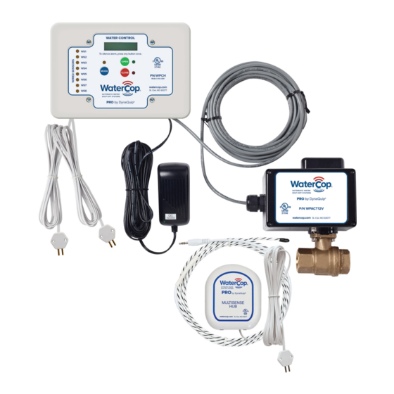
DynaQuip WaterCop WROPE6 Kullanım Kılavuzu ve Kurulum Kılavuzu - Sayfa 15
Kontrol Sistemleri DynaQuip WaterCop WROPE6 için çevrimiçi göz atın veya pdf Kullanım Kılavuzu ve Kurulum Kılavuzu indirin. DynaQuip WaterCop WROPE6 16 sayfaları.

Emergency Procedures
In the unlikely event that the WaterCop® Pro System should shut off the main water supply and
then become inoperable due to a power outage or damage, it is possible to manually operate
the WaterCop® Pro to return water service . Unplug the Water Control Panel from its power
source . The valve may be manually operated by turning the manual override handle in the
direction indicated on the indoor actuator .
For outdoor shut-off valves, unplug the Water Control Panel from its power source . Remove the
four bolts connecting the brass valve to the black actuator enclosure located outdoors . Lift the
actuator off the brass valve (water will be contained) to expose the valve stem . Now, the valve
stem can be manually turned using a screwdriver, pliers, wrench or the like .
General Safety Information
Warnings and Precautions
WARNING!
to use the unit as a step. This will cause damage to the unit and could cause personal injury. Do not
store highly flammable items such as oily rags or other combustibles near your WaterCop® Pro.
WARNING!
system. Failure to do so could result in personal injury. Do not use the case as leverage when
mounting this unit or tightening fittings. Apply wrench to flats on the valve body to tighten fittings.
INFORMATION
to protect against electrical surges that could damage the system. To insure continued functionality
of the system, it is recommended that periodic testing be performed. Dip sensor probes into a cup
of tap water and check for valve closure. Address any issues immediately.
Periodic System Maintenance & Testing
Quarterly testing and maintenance are recommended .
1 . Ensure that the sensor probes/pins are clean and free of dust/dirt .
2 . Wet sensor pins to activate valve closure/s .
3 . Verify valve closure/s .
4 . Repeat steps with the rest of the sensors .
5 . Replace sensor/s to optimal location for leak detection if disturbed .
6 . Use green button to re-open the valve each time .
Use the Maintenance Log below to record maintenance dates .
Maintenance Log
The motorized drive unit case is not capable of supporting any loads. Do not attempt
It is recommended that eye protection be worn while installing or servicing the
It is recommended that the system be plugged into a surge protection device
15
