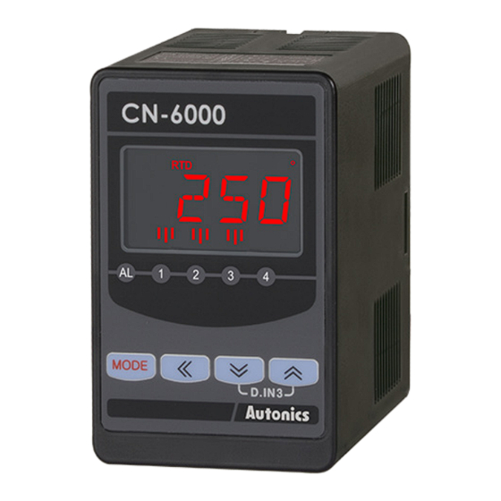
Autonics CN-610 Series Ürün Kılavuzu - Sayfa 2
Medya Dönüştürücü Autonics CN-610 Series için çevrimiçi göz atın veya pdf Ürün Kılavuzu indirin. Autonics CN-610 Series 6 sayfaları. Isolated converters

Ordering Information
This is only for reference, the actual product does not support all combinations.
For selecting the specified model, follow the Autonics website.
CN
-
6
❶
❷
❶ Input
10: Universal input
40: Pulse input
❷ Power supply
0: 100 - 240 VACᜠ ± 10 % 50 / 60 Hz
1: 24 VDCᜡ ± 10 %
Product Components
• Product
• 8-pin socket (output: C1, V1, R1 model)
Dimensions
• Unit: mm, For the detailed drawings, follow the Autonics website.
50
■ 8-pin socket
■ 11-pin socket ■ Panel cut-out
Input Type Selection Switch
• Select the input type of the universal input model.
The pulse input model does not have this input type selection
switch.
• After selecting the input type with the switch, set the same
input specification in the input type parameter of the program
mode.
Switch
mA (default)
10V
TC, RTD, mV, ±1V
-
❸
❸ Output
C1: Transmission (DC 0 - 20 mA) output × 1
C2: Transmission (DC 0 - 20 mA) output × 2
V1: Transmission (0 - 10 VDCᜡ) output × 1
V2: Transmission (0 - 10 VDCᜡ) output × 2
R1: Alarm output × 1
R2: Alarm output × 2
R4: Alarm output × 4
• Instruction manual
• 11-pin socket (output: C2, V2, R2, R4 model)
80
Ø 4.5
40
≥ 51
Input
0 (4) to 20 mA
-1 to 10 VDCᜡ
Thermocouple, RTD, mV, ± 1 VDCᜡ
Unit Descriptions
7
2
1
3
5
4
6
No. Part name
Name plate
Display part
1
-
(red, green, yellow)
2
Unit display part (red) -
Output scale bar
3
Alarm output
indicator
4
MODE key
[MODE]
5
Setting key
[◀], [▼], [▲]
6
Digital input
D.IN3
Input type display
7
-
part
01)
01) In case of thermocouple type, L, N, U, P types are not displayed.
In case of RTD type, RTD is displayed.
Connections
• SOURCE: 100 - 240 VACᜠ 50 / 60 Hz 8 VA
24 VDCᜡ 3 W
■ Universal input (8-pin)
ISOLATION
Analog TC RTD
3
+
+
+
A
-
Amp.
4
-
-
-
B
b
5
-
+
+24V
6
2-wire transmitter
01)
01) When using 2-wire transmitter, short between no.4 and 5 terminals.
■ Universal input (11-pin)
ISOLATION
Analog TC RTD
5
+
+
+
A
-
ISOLATION
Amp.
6
-
-
-
B
b
4
-
+
+24V
3
2-wire transmitter
01)
01) When using 2-wire transmitter, short between no.4 and 6 terminals.
■ Pulse input (8-pin)
NPN open
collector
Pulse
Contact
Voltage
02)
01)
In+
3
In-
OUT
4
G
G
5
+24V
+24V
6
01) Connect external resistance 10 kΩ (≥ 1/2W) to no.3 and 6 terminals for NPN open collector input.
02) Connect external resistance 10 kΩ (≥ 1/2W) to no.3 and 5 terminals for contact input.
■ Pulse input (11-pin)
NPN open
collector
Pulse
Contact
Voltage
02)
01)
In+
5
In-
6
OUT
G
G
4
+24V
+24V
3
01) Connect external resistance 10 kΩ (≥ 1/2W) to no.3 and 5 terminals for NPN open collector input.
02) Connect external resistance 10 kΩ (≥ 1/2W) to no.4 and 5 terminals for contact input.
Function
Run mode: Displays current measured value.
Set mode: Displays parameters.
• Color selectable
-
[Transmission output model]
Displays output as % by scale bars.
[Alarm output model]
Turns ON when the alarm output is on.
Used to enter monitoring mode and program
mode , move to parameters, save SV and
return to RUN mode.
Used to change parameter SV.
Press the [▼] + [▲] keys for 3 sec, it operates
the set function at digital input key parameter.
[Universal input model]
Turns ON when checking or changing the
setting value.
OUTPUT
1
+
+
+
CIRCUIT
mA
V
2
-
-
-
7
ᜠ
8
SOURCE
POWER CIRCUIT
ALARM 1
OUTPUT1
1
ALARM 1
+
+
CIRCUIT
mA
V
2
-
-
ALARM 2
9
ALARM 3
OUTPUT2
10
+
+
CIRCUIT
ALARM 4
mA
V
11
ALARM 2
-
-
7
ᜠ
8
SOURCE
POWER CIRCUIT
ISOLATION
OUTPUT
1
+
+
+
CIRCUIT
mA
V
2
-
-
-
7
ᜠ
8
SOURCE
POWER CIRCUIT
ALARM 1
ISOLATION
OUTPUT1
1
+
+
CIRCUIT
mA
V
2
-
-
ALARM 2
9
ISOLATION
ALARM 3
OUTPUT2
10
+
+
CIRCUIT
ALARM 4
mA
V
11
-
-
7
ᜠ
8
SOURCE
POWER CIRCUIT
