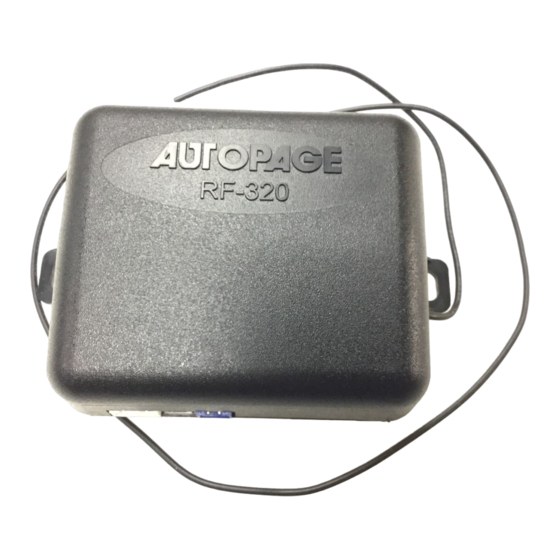
Autopage RF-320 Kurulum Kılavuzu - Sayfa 5
Güvenlik Sistemi Autopage RF-320 için çevrimiçi göz atın veya pdf Kurulum Kılavuzu indirin. Autopage RF-320 12 sayfaları. Professional vehicle security system

H3/8 . GRAY WIRE – (-) 200mA PROGRAMMABLE OUTPUT –
CHANNEL 2 OUTPUT (Factory default setting)
This wire will provide a 1 second pulse ground when you press and hold the
button on the transmitter for two seconds. The current capacity of this wire is 200 mA.
This feature allows you to operate remote control trunk release or other electric
devices.
2 STEPS UNLOCK OUTPUT
(Set Feature B – 3 Programming to "2 Step Door Unlock Output)
The 2 steps unlock feature will work for the most fully electronic door lock circuit. The
vehicle must have an electronic door lock switch, which locks and unlocks all of
vehicle's doors. When wired for this feature, press the
will disarm and unlock the driver's door only. If you press the
within 3 seconds, the alarm will disarm and unlock all doors.
H4: RF ANTENNA - BLACK THIN WIRE
The black thin wire on the control module is the receiver antenna wire. Antenna placement
is very important! Ensure that it is unwrapped and stretched out with the last 6" straight and
keep it away from large metal objects or chassis for best reception.
H7: 3 PIN DOOR LOCK CONNECTOR:
3 Pin Mini - Connector
Blue Wire
Green Wire
5-WIRE ALTERNATING DOOR LOCK
Green Wire
3 Pin Plug
87
To Alarm
87
Blue Wire
( - ) 200mA Unlock Pulse
( +) 200mA Lock Pulse
( - ) 200mA Lock Pulse
( + ) 200mA Unlock Pulse
Master Door
Lock Switch
Splice
86
Cut the Existing
X
Unlock Wire
87a
30
85
Splice
+12V
86
87a
30
85
To Slave Door
Lock switches
5
button one time, the alarm
button two times
+12V
Cut the Existing
X
Lock Wire
To Door
Lock
Motor
