Dynatech PR-2000 UD Kullanım ve Bakım Kılavuzu için Talimatlar - Sayfa 10
Endüstriyel Ekipmanlar Dynatech PR-2000 UD için çevrimiçi göz atın veya pdf Kullanım ve Bakım Kılavuzu için Talimatlar indirin. Dynatech PR-2000 UD 18 sayfaları.
Ayrıca Dynatech PR-2000 UD için: Kullanım Kılavuzu (11 sayfalar)

INSTRUCTIONS : PR-2000-UD
Date : 20/10/2020
Revision : 10
Lower limit
505
P+Q (Kg)
537
Upper limit
577
Loads may be duplicated through configuration of this tandem safety gear. See Manual DYN 37/8 – Extendible
T25UD/T25 Tandem safety gear for further information.
3 INSTALLATION AND ADJUSTMENT
3.1 ASSEMBLY ON THE FRAME
The holes should be made on the frame's uprights to secure the safety gear, according to the dimensions and
position displayed in the safety gear drawings attached (DYN 07.C002.00), ensuring that the guide rail's axis
is centred with the frame.
To secure the safety gear onto the frame, we recommend a 79.09 Nm tightening torque for grade 8.8 M12
bolts, and of 111 Nm for grade 10.9 bolts.
Figure 2: Assembling the safety gear onto the
frame (1)
�
�
�
Safety gear position:
a) The safety gears should be assembled in the position displayed in Figure 4
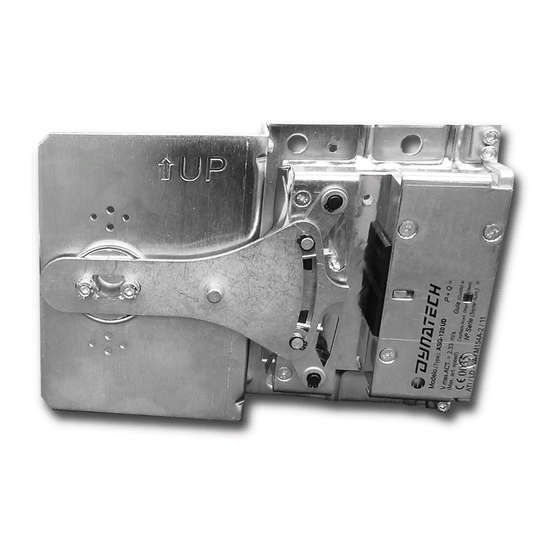
b) A circle on one of the safety gear's ends will indicate its upper part. This mark should always be on
the upper part during the assembly.
c) There should be an additional mark on the protection plate including the word "UP" and an arrow
indicating the safety gears' upright position.
Cod : DYN 07.01.10
574
665
621
719
668
773
Figure 3: Assembling the safety gear onto the frame (2)
771
843
974
834
911
1053
843
979
1132
1130
1222
1314
4
