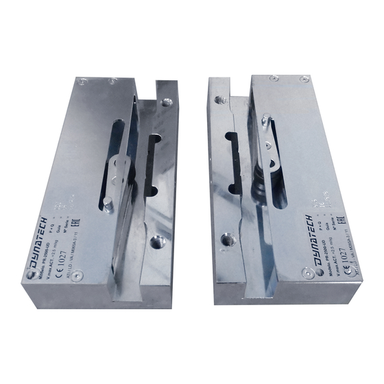
Dynatech PQ-4000 UD Kullanım ve Bakım Kılavuzu için Talimatlar - Sayfa 14
Güvenlik Ekipmanları Dynatech PQ-4000 UD için çevrimiçi göz atın veya pdf Kullanım ve Bakım Kılavuzu için Talimatlar indirin. Dynatech PQ-4000 UD 19 sayfaları. Progressive safety gear
Ayrıca Dynatech PQ-4000 UD için: Kullanım Kılavuzu (11 sayfalar)

INSTRUCTIONS: PQ-4000-UD
Date: 20/10/2020
Revision: 08
4 INSPECTIONS AND MAINTENANCE
4.1 CHECKING THE SAFETY GEARS
For the safety gears to function correctly, their proper assembly and adjustment must be verified as well as
the sturdiness of the unit's connection to the car and the guide rails, as is stated in the standard EN 81:20 and
EN 81:50.
It is recommended to follow the standard's provisions for inspections and tests, both for commissioning and
regular testing.
The safety gear model's behaviour curves may be requested from Dynatech based on its (P+Q) and the
installation's rated load when tested dynamically with suspensions included.
The proper synchronisation of the safety gears may be checked by
verifying that the roller's track is marked on both guide rails and that
they have a similar length, with the difference between the two sections
not being more than 4 cm.
The requirements for regular tests should not be greater than those for
commissioning. It is therefore recommended to always use the same
load (P/Q) and speed conditions. For better control, the maintenance
worker should have a safety gear operation record, where he or she
records the serial number and number of operations.
inspection is sufficient to check that the installation has not been
damaged, see section 4.3.1.
It is not necessary to work on the safety gears due to their regular tests,
as long as their braking distance does not exceed double the distance
recorded from the first commissioning test.
After operating the safety gear in free fall, it is recommended to contact
Dynatech, or your nearest supplier, directly, who will indicate how to
proceed.
Cod: DYN 11.01.08
Figure 9: Safety gear synchronisation using the T-3 driving bar
A visual
Figure 10: Braking track on guide
rail
7
