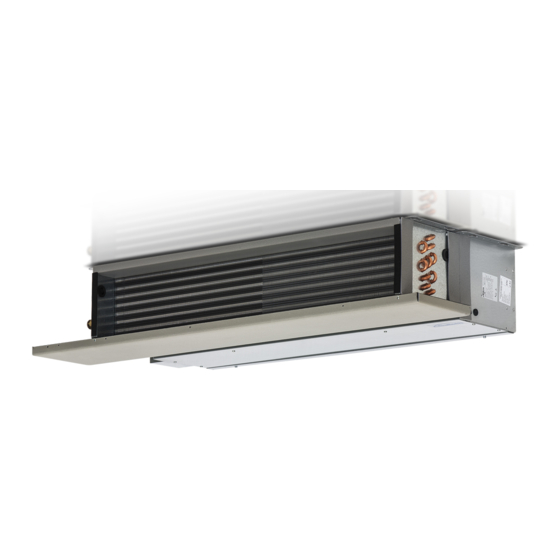
Galletti PWN Manuel - Sayfa 3
Klima Aksesuarları Galletti PWN için çevrimiçi göz atın veya pdf Manuel indirin. Galletti PWN 13 sayfaları. Outdoor air inlet motorized louvre
Ayrıca Galletti PWN için: Manuel (8 sayfalar)

SM
The outdoor air inlet motorized louvre is intended for replacing the
G B
air in the room directly from the air-handling unit. The amount of
outdoor air that will be let into the room, after having been filtered and
treated thermally, may be regulated proportionally from 0 to 100% by
means of a servomotor controlled by a rotary potentiometer that is inside
the specific CSD control, which is designed for flush wall-mounting
installations.
Kit SM, essentially comprises the following components:
Outdoor air inlet louvre made of galvanized steel sheet and setup for
being connected to the machine, at one end, and to the other required
accessories.
Servomotor connected directly to the louvre's baffle, with a protection
rating of IP54 and power supply of ~ 24V.
The louvre may be opened or closed automatically at the signal of the
external auxiliary contacts (not supplied) such as antifreeze thermostats,
timers, etc., with the possibility of connecting multi-servomotors in
parallel to an individual opening-closing control.
230V - 24V voltage transformer, complete with support terminal strip
housed inside the specific electrical box, which functions as a mechanical
protection for preventing the access to the connecting terminal strip and
to the transformer itself.
Brackets for fastening the SM louver to the air intake of the PWN unit.
Self-threading fixing screws.
The control panel for activating the servomotor (flush wall-mounting,
called CSD, to be ordered separately). It is to be remotely installed and
is to be used for closing or opening the louvre from 0 to 100%.
To prevent the water from freezing inside the heat exchanger during the
winter, close the outdoor air inlet when the system is not operational or
use an antifreeze solution checking its freezing point:
% of glycol in weight
Freezing point (°C)
INSTALLATION
Install the fastening brackets to the air intake of the unit as
shown in Fig. 1.
Fasten the SM louver to the PWN unit as shown in Fig. 2.
It is advisable to mount the air inlet louvre on the air-handling
unit before installing the unit in its final seat.
Do NOT take hold of the strap of the accessory as this may
deform the accessory thus causing it to malfunction.
Note:
It is advisable to couple the outdoor air inlet louvre with the GR intake grid
(see GR accessory card) in the model with the flat G2 filter included in
the frame.
To limit flow resistance of the sucked outdoor air, comply with the
sections indicated in figure 3. As such, even when sucking in all the fresh
air, the intake section remains at least the same at the machine's intake
inlet.
Legend of figure 3:
PWN
Air handling unit intake
INT
Recycled air (indoor air)
EXT
Fresh air (outdoor air)
Install a flush-mounted remote control panel as shown in figure (4).
Make the electrical connections complying with the diagrams in figures
5 and 6 that show the following items:
Figure 5: CSD with one SM;
Figure 6: CSD with more than one SM (10 at the most).
È severamente vietata la riproduzione anche parziale di questo manuale / All copying, even partial, of this manual is strictly forbidden
0
10
20
30
0
-4
-10
-16
The following abbreviations are used in the diagrams:
CSD
- Remote control
F
- Protection fuse (not supplied)
IL
- Line circuit breaker (not supplied)
NM24SR
- Louvre servomotor
M
- Terminal strip
T
- Transformer 230/24V
A, B
- Auxiliary contacts not supplied (antifreeze thermostat, etc.):
A open + B open = Indoor air 100%
A open + B closed = Outdoor air 100%
A closed + B open = Adjustment 0 to 100%
A closed + B closed = Outdoor air 100 %
1
Unit power line
Power supply of succeeding motors
2
Make the electrical connections, with power OFF, conforming
to the prevailing safety regulations.
Each unit
requires a switch (IL) on the feeder line with a
distance of at least 3 mm between the opening contacts, and
a suitable safety fuse (F).
The installer is in charge of carrying out the hatched
connections.
If more than one louvre is connected to an individual CSD
control, wire everything as indicated in the diagram of figure 6.
In this case, provide a 24V-power supply line by sizing the
transformer (T) according to the number of expected louvres.
The consumption of every single servomotor is 5 VA.
The louvres may be connected in parallel to a unique control up to a
maximum of 10.
40
OPERATION
-24
The louvre is operated by the control panel that contains the rotary
potentiometer that regulates the opening of the louvre in proportional
mode.
On setting the control to 100%, the position of the louvre is that of total
outdoor air inlet. Vice versa on setting the control to 0%, the position of
the louvre is that of total ambient air recycle.
The serigraphy on the control panel indicates the percentage of the fresh
air.
CLEANING OF THE AIR FILTER
At regular intervals, clean the filter on the fresh air line and the filter on
PWN unit.
3
G B
UT 66000695 - rev. 00
