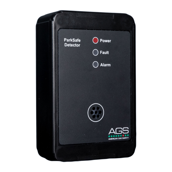
AGS Parksafe Control Panel Kurulum Operasyon ve Bakım - Sayfa 4
Kontrolör AGS Parksafe Control Panel için çevrimiçi göz atın veya pdf Kurulum Operasyon ve Bakım indirin. AGS Parksafe Control Panel 16 sayfaları. Ventilation control panel
Ayrıca AGS Parksafe Control Panel için: Kurulum ve Kullanım Kılavuzu (16 sayfalar), Kurulum ve Kullanım Kılavuzu (16 sayfalar), Kurulum, Çalıştırma ve Bakım Kılavuzu (20 sayfalar)

Installation, Operation & Maintenance
Parksafe Control Panel
Installation
Typical Location and Positioning
The Parksafe control panel is designed for installation into car parking facilities and enclosed garages. It is designed to be
paired with AGS Parksafe Gas Detectors (Nitrogen Dioxide and Carbon Monoxide) that will be linked via MODBUS back
to the control panel and monitor the connected detectors in numbers up to 16 (per control panel) and automatically
control ventilation systems according to gas levels and an optional temperature level.
The Parksafe will make or break a dry contact internally on terminals: OUTPUT 1 and a second contact on OUTPUT 2.
This is to have a live feed to the ventilation system wired through the contact so that the Parksafe can activate ventilation/
fans, this can either be via a direct live feed or via a run signal. There is another output relay that will activate after
OUTPUT 2 has been activated for an optional extended period of time. This can be used for a link to the BMS or other
external indication device.
The Parksafe also has a 0-10VDC output to allow the panel to drive VSD's based on gas level outputs. The Parksafe
control panel is designed to be located in an office or other suitable area within a carpark not accessible to the public.
Please refer to your detector manual for important information regarding coverage, location and positioning including areas
and conditions to avoid!
Place the control panel in accordance with regulations ensuring optimum access and monitoring.
The control panel should be located outside of the hazardous area that it is monitoring. Easy accessibility is required both
for status observation and alarm purposes.
The quality of the data signals will vary depending on cable size, number of detectors, the quality and length of the cable run.
Where connections may exceed 500 yards from one control panel. Contact your supplier should issues occur!
The use of sound strobes are highly recommended!
Rev: 13
0721
4
