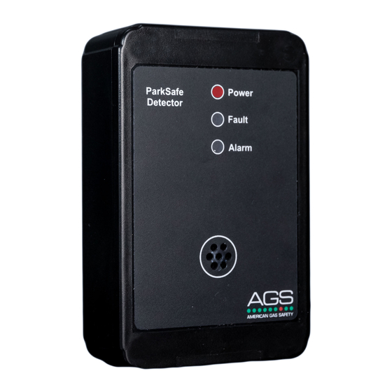
AGS Parksafe Control Panel Kurulum, Çalıştırma ve Bakım Kılavuzu - Sayfa 6
Kontrol Paneli AGS Parksafe Control Panel için çevrimiçi göz atın veya pdf Kurulum, Çalıştırma ve Bakım Kılavuzu indirin. AGS Parksafe Control Panel 20 sayfaları. Ventilation control panel
Ayrıca AGS Parksafe Control Panel için: Kurulum ve Kullanım Kılavuzu (16 sayfalar), Kurulum ve Kullanım Kılavuzu (16 sayfalar), Kurulum Operasyon ve Bakım (16 sayfalar)

Installation, Operation & Maintenance
Electrical Connections
Access to the interior of the controller, when carrying out any work, must be conducted by a competent person!
Where cable glands are used for wire entry, use no bigger than 20mm (3/4") separated by at least 20mm (1/2")!
Any parts that form part of the enclosure - connections/installation must have a minimum fire-retardant rating of UL 94 V-1!
External wiring routed through the 'volt free' relays (Output 1 & 2, Alarm and Damper) require double insulated wiring for safety!
Be careful when creating access for cables – Damage to circuit boards will void any warranty!
Before carrying out any work ensure local regulations and site procedures are followed!
For Modbus communications, a shielded cable is used!
For field connections use wires suitable for at least 90°C (194°F)
Isolate the equipment from all hazardous live power sources before opening the cover!
A switch or circuit breaker must be included in the installation! It must be suitably located and easily reached to allow for
disconnection of the equipment! It must be marked as the disconnecting device of the equipment!
If you are encountering noise or irregular problems with a Modbus link, the problem is likely related to grounding, incorrect
shielding or wiring mains power next to Modbus wiring.
1.
POWER/ LINE IN.
The ParkSafe controller requires a power supply of 100-120Vac using a 3A switched fused spur. When mains
line, power is connected to the controller, a red LED will illuminate on the front of the controller (AGS Logo).
2.
OUTPUT-1.
Switches when a ParkSafe detector reaches 'pre-alarm' status. The [0-10v Output] will send 5v signal.
3.
OUTPUT-2.
Switches when a ParkSafe detector reaches 'alarm' status. The [0-10v Output] will send a 10v signal.
4.
ALARM.
Switches following the [OUTPUT 2] relay when a ParkSafe detector remains in alarm status.
A delay time of 5,10,15,20 or 25 minutes is selectable in the system configuration settings.
5.
DAMPER.
Switches together with either [Output-1], [Output-2] or [Alarm] relays - selectable in the system settings.
Rev: 20
ParkSafe Controller
6
