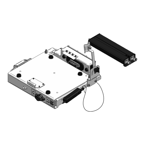
Gamber Johnson 7160-0377 Kurulum Talimatları Kılavuzu - Sayfa 9
Yerleştirme İstasyonu Gamber Johnson 7160-0377 için çevrimiçi göz atın veya pdf Kurulum Talimatları Kılavuzu indirin. Gamber Johnson 7160-0377 10 sayfaları. Military docking station

1. J1 pins 1, 5 and 6 = Input Power (+28Vdc)
2. J1 pins 2, 3 and 4 = Input Power Ground
3. J2 pins 1-14 and 21 = Video Output
4. J2 pins 15-17 and 22 = USB/Ethernet Output
a.
USB_TXN = Transmit Data Negative Signal
b. USB_TXP = Transmit Data Plus Signal
c.
USB_RXN = Receive Data Negative Signal
d. USB_RXP = Receive Data Plus Signal
5. J2 pins 18-20 = Audio Output
a.
HP_R = Headphone Right Audio Output
b. HP_L = Headphone Left Audio Output
c.
AGND = Audio Ground
6. J3 pins 1-6 and 20-21 = 1GHz Ethernet
a.
PPTMDI2- = Bi-Directional pair 2- or C- (J3-1)
b. PPTMDI2+ = Bi-Directional pair 2+ or C+ (J3-2)
c.
PPTMDI1- = Bi-Directional pair 1- or B- (J3-3)
d. PPTMDI1+ = Bi-Directional pair 1+ or B+ (J3-4)
e.
PPTMDI0- = Bi-Directional pair 0- or A- (J3-5)
f.
PPTMDI0+ = Bi-Directional pair 0+ or A+ (J3-6)
g.
PPTMDI3- = Bi-Directional pair 3- or D- (J3-20)
h. PPTMDI3+ = Bi-Directional pair 3+ or D+ (J3-21)
7. J3 pins 7-10 = USB Port
a.
USB4_PWR = USB #4 Port +5Vdc
b. USBDP4 = USB #4 Port Data +
c.
USBDM4 = USB #4 Port Data-
d. USB4_GND = USB #4 Port Ground
8. J3 pins 11-14 = USB Port
a.
USB3_PWR = USB #3 Port +5Vdc
b. USBDP3 = USB #3 Port Data +
c.
USBDM3 = USB #3 Port Data-
d. USB3_GND = USB #3 Port Ground
9. J3 pins 15-17 and 22 = Auxiliary +5Vdc Output max 4 amps
a.
+5VDC = +5 Volts Output (J3-16 & 17) (4 Amps max when combined)
b. +5VDC_GND = +5 Volts Output Return (J3-15 & 22)
10. J4 pins 1-5 and 18-21 = Serial Port #2
11. J4 pins 6-14 = Serial Port #1
12. J4 pins 15-17 and 22 = USB Port
a.
USB2_PWR = USB #2 Port +5Vdc
b. USBDP2 = USB #2 Port Data +
c.
USBDM2 = USB #2 Port Data-
d. USB2_GND = USB #2 Port Ground
Pin Acronyms List for 7160-0377
