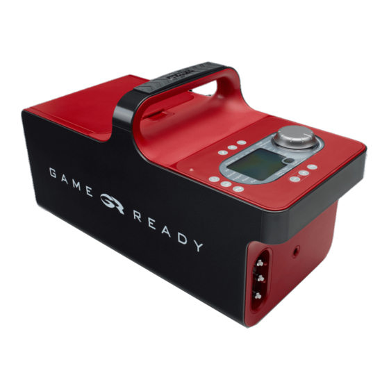
Game ready GRPro 2.1 Kullanıcı Kılavuzu - Sayfa 11
Tıbbi Ekipman Game ready GRPro 2.1 için çevrimiçi göz atın veya pdf Kullanıcı Kılavuzu indirin. Game ready GRPro 2.1 12 sayfaları. Cold & compression therapy

table 4 for rf immunity
reCOmmended sepArAtiOn distAnCes Between pOrtABLe
And mOBiLe rf COmmuniCAtiOns equipment And tHe grprO
The GRPro
™
2.1 is intended for use in an electromagnetic environment in which radiated RF
disturbances are controlled. The customer or the user of the GRPro
electromagnetic interference by maintaining a minimum distance between portable and mobile RF
communications equipment (transmitters) and the GRPro
the maximum output power of the communications equipment.
sEparation distanCE aCCording to FrEquEnCY oF transmittEr
ratEd maximum output
powEr oF transmittEr
150 kHz to 80 mHz
W
d = 1.2 √P
0.01
0.12
0.1
0.38
1
1.2
10
3.8
100
12
For transmitters rated at a maximum output power not listed above, the recommended separation
distance d in meters (m) can be estimated using the equation applicable to the frequency of the
transmitter, where P is the maximum output power rating of the transmitter in watts (W) according to
the transmitter manufacturer.
NOTE 1 At 80 MHz and 800 MHz, the separation distance for the higher frequency range applies.
NOTE 2 These guidelines may not apply in all situations. Electromagnetic propagation is affected by
absorption and reflection from structures, objects and people.
wArnings:
medical electrical equipment needs special precautions regarding emC and needs to
be installed and put into service according to the emC information provided in the
user's manual.
portable and mobile rf communications equipment can affect medical electrical
equipment.
the grpro
2.1 system has to be powered with the AC adapter models globtek
™
#gtm-21097-5012 or fsp group inc. #fsp030-rCAm in order to be compliant with
ieC/en 60601-1-2 section 6.1 and 6.2 emC requirements.
the use of accessories, transducers and cables other than those specified and sold
by the manufacturer of the grpro
components may result in increased emissions or decreased immunity of the medical
electrical system.
the grpro
™
2.1 system should not be used adjacent to or stacked with other
equipment. if adjacent or stacked use is necessary, the grpro
observed to verify normal operation in the configuration in which it will be used.
the essential performance of the grpro
Compression Cycle:
High: cyclic 5-75mm Hg
med: cyclic 5-50 mm Hg
Low: cyclic 5-15 mm Hg
nO pressure: wrap shall be vented to atmosphere
the cooling temperature of the circulating ice water will be adjustable between
34°f (1°C) and 50°f (10°C) as long as the ice water in the ice box is supplied with
sufficient amount of ice.
EN- 18
™
2.1 can help prevent
™
2.1 as recommended below, according to
80 mHz to 800 mHz
800 mHz to 2.5 gHz
d = 1.2 √P
d = 2.3 √P
0.12
0.38
1.2
3.8
12
2.1 system as replacement parts for internal
™
™
2.1 system should be
2.1 system is:
™
2.1
™
error
0.23
0.73
2.3
7 .3
23
t r o u b l e s H o o t i N G
WHAt does
it MeAN?
•
Air Pressure sensor: The
This is most likely to occur if you have
Control Unit has detected a
restarted the System with an inflated Wrap
problem calibrating the air
attached.
•
pressure circuit on start-up.
Detach the Wrap, pressing it flat to expel
the air accumulated inside and try again.
self-test error – Air
•
Disconnect the Wrap from the Control Unit.
Pump: The Control Unit
•
Turn the Control Unit off and on again
has detected an electronic
without a Wrap connected.
•
problem in the air circuit on
Reconnect the Wrap and resume treatment.
•
start-up.
If the problem persists, contact Customer
Service.
dry Pump: The Control Unit
•
Be sure you are using ATX Series Heat
Exchangers.
has detected a dry pump.
•
Note that if you are using new Wraps,
In order to prevent possible
the water in the reservoir may have been
damage to the fluid pump,
depleted and causing this error. Make sure
the unit will stop therapy.
there is adequate water in the reservoir
based on the fill line indicator label. Refer to
instructions for priming a Wrap below.
•
Verify that the ice box filter is not clogged
(refer to filter maintenance instructions on
page 10).
•
Make sure there are no kinks in the Wrap or
Connector Hose.
•
Turn the Control Unit off and on again.
•
Disconnect and reconnect the hose from the
Control Unit and the Wrap, verifying that an
audible "click" is heard at both connection
points.
•
Prime the Wrap using the following steps:
- Select "No Pressure."
- Attach the hose to the unit and the wrap.
- Lay the Wrap open and flat next to or
lower than the Control Unit (not on the
body).
- Run the System for 2 minutes.
•
Prime the Control Unit using the following
steps:
- Disconnect the hose from the Control Unit.
- Now, look at the Wrap connection location
on the Control Unit. On the top valve,
push the white prong in so that it is flush
with the metal connector.
- Make sure you are not fully covering the
opening in the prong.
- Push start, and water should squirt out of
the valve.
- Restart the System.
•
over Pressure: Indicates
Turn the Control Unit off and back on.
•
that the Control Unit has
Make sure the Wrap is applied securely
exceeded the target air
around the body.
•
pressure.
Try using a different Wrap and Hose to
isolate which component may be producing
the error. For example, an error which
occurs with a Shoulder Wrap but not a Knee
Wrap may indicate that the Shoulder Wrap
is causing the error: not the Knee Wrap or
Control Unit.
WHAt CAN
i do?
EN-19
