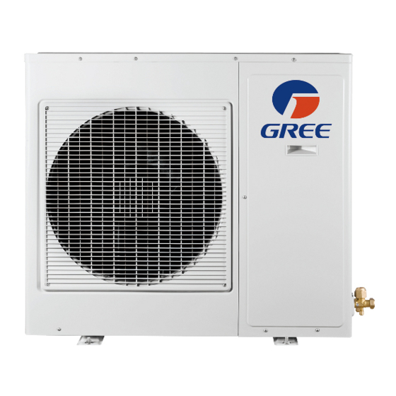
Gree GWHD(24)ND3CO Kurulum Kılavuzu - Sayfa 11
Isı Pompası Gree GWHD(24)ND3CO için çevrimiçi göz atın veya pdf Kurulum Kılavuzu indirin. Gree GWHD(24)ND3CO 16 sayfaları. Multi
ductless inverter
Ayrıca Gree GWHD(24)ND3CO için: Kullanıcı El Kitabı (11 sayfalar)

- 1. Heat Pump
- 2. Installation Manual
- 3. Table of Contents
- 4. Safety Precautions
- 5. System Requirements
- 6. Suggested Tools
- 7. Site Instructions
- 8. Dimensions
- 9. Indoor Unit
- 10. Outdoor Unit
- 11. Refrigerant Piping
- 12. Refrigerant Piping
- 13. Power and Wiring
- 14. Vacuum Testing
- 15. Start-Up
- 16. Troubleshooting
INSTALLATION OF POWER AND WIRING
Step 8
Indoor Unit Interconnecting Wire Connections
W RNING
Disconnect all electrical power to unit including disconnects,
fuses and circuit breakers.
1. Open front cover of indoor unit and remove field wiring terminal block cover.
2. Pull interconnecting wires up from back of indoor unit and position in close to the
terminal block on indoor unit.
NOTE: The indoor unit is powered from the outdoor unit, depending on local code,
a disconnect switch may need to be installed to a power supply circuit.
3. Connect wiring to indoor unit per connection diagram.
NOTE: Record wire colors and terminal references for uses with Outdoor Unit
wire connections.
4. Replace field wiring cover and close front cover of indoor unit.
INSTALLATION OF POWER AND WIRING
Step 9
Outdoor Unit Wire Connections
W RNING
Disconnect all electrical power to unit including disconnects,
fuses and breakers.
1. Remove the service panel on right side of the outdoor unit.
2. Insert interconnecting wires and main power wires
through the wire holes on conduit mounting bracket.
3. Secure main power conduit (and interconnecting
wire conduit, if required) with locking nuts to
conduit mounting bracket
4. Open wire clamp/strain relief and adjust wire
lengths for proper connections to the outdoor unit
terminal block.
5. Following the same wire color and terminal references
from the indoor unit, tightly connect each interconnecting
wire to the terminal block per wiring diagram below.
NOTE: Crossing interconnecting wires will cause system malfunction and possible damage.
19
Multiple Port Conduit
Mounting Panel
(Reference Only)
Interconnecting
Wires
Main Power Wires
Multiple Port Cable
Connections
(Reference Only)
20
