Airflow 7106A Garanti ve Kurulum Talimatları - Sayfa 2
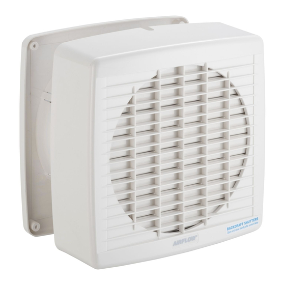
Fan Airflow 7106A için çevrimiçi göz atın veya pdf Garanti ve Kurulum Talimatları indirin. Airflow 7106A 4 sayfaları. Maxair wall exhaust fan
Ayrıca Airflow 7106A için: Kurulum Talimatları (4 sayfalar)
1.
Check that the proposed location of the fan will
not foul joists, existing wiring or other internal
wall features (wall thickness between 110
and 310mm). Use template provided to mark
out hole. Cut a hole through the wall ø230mm.
Screw fan assembly to internal wall via 4
corner openings, see fig. A. (Appropriate
fasteners to be used for each installation
not provided.)
1
2
FAN
ASSEMBLY
3
2.
Remove Termination Cover see fig B (screws
marked with "1", "2", "3").
3.
Electrician to make electrical connections as
shown, using 3 core, 1mm
Termination Cover.
2
7106A connection diagram
7108A connection diagram
Fig A
4.
With fan assembly mounted on the internal
wall, cut PVC sheet to suit wall depth.
Fig B
2
cable. Replace
Fig B