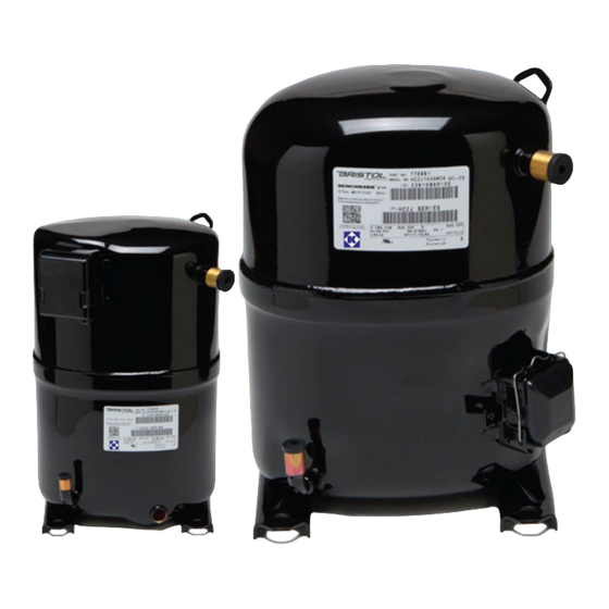
Bristol H29B24UABH Kurulum ve Servis Talimatları Kılavuzu - Sayfa 5
Hava Kompresörü Bristol H29B24UABH için çevrimiçi göz atın veya pdf Kurulum ve Servis Talimatları Kılavuzu indirin. Bristol H29B24UABH 18 sayfaları. Refrigeration/air conditioning/heat pump compressors

9.
CHARGE THE SYSTEM. When a vacuum of at least 200 microns is reached, close gauge valve, remove
vacuum pump, and break the vacuum using system refrigerant vapor. Never dump liquid refrigerant into
the compressor. Liquid can be used to break the vacuum if it is connected to the liquid line, not the
discharge line.
Charge the system according to the manufacturer's specifications. Be sure to compensate the charge for
the addition of the filter drier. Consult unit pressure/superheat chart on the unit door panel for the correct
superheat since pressures and superheat change with the ambient temperature.
WEIGHING in the system charge to the factory specification will help point out system faults that
may still exist.
10.
START-UP. CLAMP-ON AMMETER MUST BE IN PLACE BEFORE POWER IS APPLIED TO MONITOR
START WINDING CURRENT ON START-UP!! See page 6
ASSURE THESE NORMAL START WINDING CURRENTS ON START-UP
CONFIGURATION
NORMAL START WITH RUN CAP ONLY
NORMAL START WITH RUN AND START CAP
NORMAL START WITH START CAP (INDUCTION RUN)
WARNING: If above currents are exceeded for more than 5 seconds, disconnect power and
correct the fault before restarting.
NOTE: Assure voltage to compressor does not drop below minimum allowable voltage (eg. 197
volts for 230/208-1-60) during the period the compressor is trying to start. Refer to page 2
for explanation of test to check LOCKED ROTOR PULL-DOWN VOLTAGE.
2 - 10 AMPS
20 AMPS AND DROP TO 2-10 AFTER START
20 AMPS AND DROP TO 0 AFTER START
Page 5
APPROX. CURRENT
