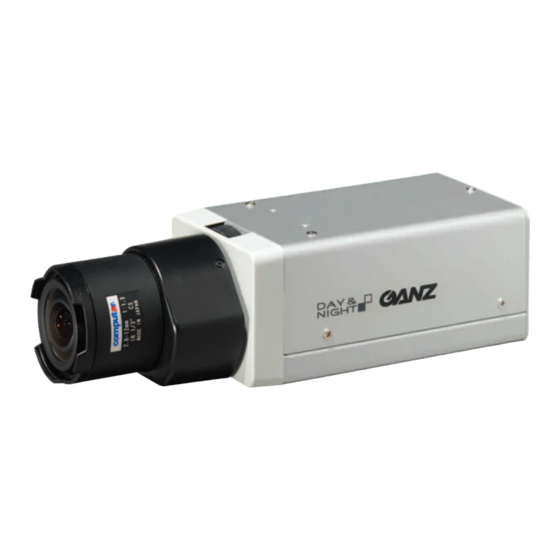
Ganz YCX-05N Kullanım Kılavuzu - Sayfa 5
Güvenlik Kamerası Ganz YCX-05N için çevrimiçi göz atın veya pdf Kullanım Kılavuzu indirin. Ganz YCX-05N 8 sayfaları. Ganz ycx-05 series color day/night camera wide dynamic range
Ayrıca Ganz YCX-05N için: Teknik Özellikler (2 sayfalar)

Easy focus adjustment
Make sure to adjust focus in a bright light envi-
ronment. With the OSD screen not displayed,
activate the focus adjustment screen by press-
ing and holding down the Menu Operation
Switch in the UP direction (Jump function).
You can also activate the focus adjustment
screen by selecting "Setup" "EZ Focus" in
the OSD menu. The lens iris is forcibly kept
open while this screen is being displayed. The
focus can be easily adjusted by using focus
adjustment assisting functions such as edge
enhancement, focus level bar indication, and
screen view zoom-up/down enabled by press-
ing the Menu Operation Switch in the left/right
direction. When the adjustment is completed,
close the OSD menu.
* For details, please see "EZ Focus Menu"
of the separate "OSD Operation Manual."
5 Video output connector
Connected to the TV monitor with a coaxial
cable.
6 Power input terminal
(when using 12 V DC/24 V AC)
This model can use 24 V AC and 12 V DC.
:
Use only with a 24 V AC power supply
marked class 2 or +12 V DC power supply.
12V DC connection
When connecting to a terminal
When connecting a cable to a power cable
terminal (AWG16-24), peel off the cable by
11 mm from the end.
11 mm
7 Auto-iris output connector
For connecting the cable of an auto-iris lens,
the pin assignment is as shown below. (While
using the auto-iris lens, set the Auto-iris
Mode switch (3) to "DC" or "VIDEO"
depending on the type of lens used.)
No.
DC
1
CONTROL-
+9.4V (max. 50 mA)
2
CONTROL+
N. C.
3
DRIVE+
VIDEO
4
DRIVE-
GND
24V AC connection
VIDEO
8 B/W Fix terminal/Mode Selection terminal
This terminal can be used as a B/W Fix ter-
minal and also as a Mode Selection terminal
that enables the dynamic switching of OSD
settings. The mode selection setting needs
to be adjusted beforehand on the OSD set-
ting screen. The picture mode can be fixed
at B/W by shorting the two contacts on the
B/W Fix terminal. (See the back side of the
camera on page 3.) Fixing the picture mode
at B/W can prevent the picture from having
a phenomenon in which continuous switch-
ing occurs between the color mode and B/W
mode under infrared illumination. The Mode
Selection terminal allows switching between
Profile 1/Profile 2 selected on the OSD
screen.
When using infrared illumination, make sure
to adjust the focal point of the lens in color
mode.
If excessive infrared illumination causes the
phenomenon above, set the picture mode at
B/W using the BW Fix terminal.
9 RS485 communication terminal
(with communication function)
The RS485 communication function enables
remote operation of the OSD function.
* For initial settings of the camera for RS485
communication, please see "RS485 Menu"
of the separate "OSD Operation Manual."
When connecting to a terminal
While connecting a shielded twisted pair cable
to a terminal [B/W Fix terminal, Communica-
tion terminal (AWG22-26)], peel off the cable
by 9 mm from the end.
9 mm
bk Termination resistance switch
(with communication function)
Termination resis-
tance switch
During the RS485 communication connec-
tion, turn on the termination resistance switch
of the camera connected at the end of the
cable, and turn off all other switches. Adjust
the characteristic impedance of the cable
used to the same level as that of the termina-
tion resistance (120 Ω).
EG-5
TERM
OFF A+
ON
AC24V
