GAPOSA M10A Referans Kılavuzu - Sayfa 7
Endüstriyel Ekipmanlar GAPOSA M10A için çevrimiçi göz atın veya pdf Referans Kılavuzu indirin. GAPOSA M10A 11 sayfaları. Safety brake
Ayrıca GAPOSA M10A için: Referans Kılavuzu (14 sayfalar)
In order to select the most suitable model for you application, it is necessary to consider
the following characteristics:
- Nominal torque: is the reference value to select the most appropriate safety brake
according to the weight of the shutter and the diameter of the drive shaft. Within this
value must fall the nominal torque of the motor that is to be installed.
- Locking torque: is the maximum stress to which the safety brake is subjected when it
blocks the rotation of the shaft.
- Working speed: refers to the maximum number of revolutions at which the safety
brake works as a simple support without functioning as a descent stopper. Within this
value must fall the number of revolutions of the shutter shaft.
- If the safety brake is installed with a chain transmission system , make sure the chain is
not loose. A chain not sufficiently tight causes sudden accelerations and the safety
brake may accidentally block.
Then refer to Tab.1.
INSTALLATION INSTRUCTIONS
This operation is not particularly difficult, but in order to get the best performance from
the safety brake, in accordance with the criteria indicated by the producing company,
the installer should take particular care of some important prescriptions:
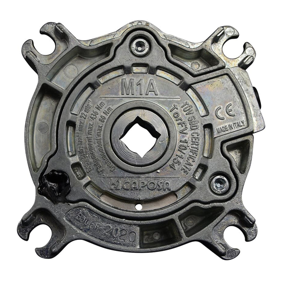
1. The safety brake must be always installed with the arrow pointing to the direction in
which the shutter descends; M1A and M2A safety brakes lock in both directions and
for this reason they can an indifferently be installed on the right or on the left side of
the shaft;
2. M1A and M2A safety brake must be installed in square and with the cable on the
top (Fig.1), the safety brakes base (from M3A to M30A) must be installed as horizontally
as possible; all safety brakes must be in square as regards the vertical level; in both
directions any deviation must not exceed ±3° (fig.1). A wrong horizontal or vertical
alignment may vary the locking speed and may cause a bad operation of the system;
3. For the base use fastening screws with a suitable diameter (ref. Tab. B); for M1A and
M2A safety brakes use M8 fastening screws;
4. Weld the support pins of the shaft concentrically to it;
EN
7