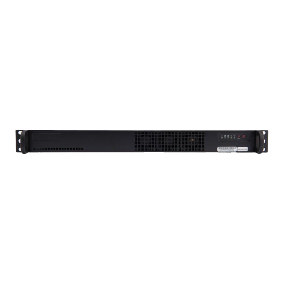
CORNING PSM-I Hızlı Kurulum Kılavuzu - Sayfa 12
Ağ Donanımı CORNING PSM-I için çevrimiçi göz atın veya pdf Hızlı Kurulum Kılavuzu indirin. CORNING PSM-I 13 sayfaları. Head end equipment

ONE SD-LAN Head
End Equipment
Quick Installation Guide
SD-LAN-000-HEEQUIP
8 Fiber Set Up |
8.1 Fiber Hardware Housing Set Up
Step 1
Mount selected fiber hardware
enclosure in Head End equipment
rack
CCH-04U
8 CCH Panels/Cassettes
CCH-03U
6 CCH Panels/Cassettes
CCH-02U
4 CCH Panels/Cassettes
CCH-01U
2 CCH Panels/Cassettes
Step 2
Insert selected fiber panels or
cassettes into housing
NOTE: Outgoing fiber cables can be terminated using
the following methods
A. Unicam® Connectors
B. Fuselite® Connectors
C. CCH Pigtailed Splice Cassettes
METHOD A. Unicam® Connector
Step 1
Use CCH panels to interconnect
Head Equipment and outgoing fiber
cables
Step 2
Insert CCH panels into fiber housing
Qucik Installation I SD-LAN-000-HEEQUIP
Step 3
Terminate outgoing fiber using
Corning Unicam® standard
recommended procedure
(https://www.corning.com/
catalog/coc/documents/standard-
recommended-procedures/006-369.
pdf)
Step 4
Plug terminated Unicam connectors
into the back of the CCH panels
Step 5
Route fiber in back of CCH housing
making sure the minimum bend
radius is not exceeded and
fibers are not pinched or damaged
Step 6
Make sure outgoing cables are
routed and strain relieved properly to
housing
Step 7
Connect jumpers from Head End
Active equipment to the appropriate
port on CCH panels
METHOD B. Fuselite® Connector
Step 1
Use CCH panels to interconnect
Head Equipment and outgoing fiber
cables
Step 2
Insert CCH panels into fiber housing
Step 3
Terminate fiber using Corning
Fuselite® standard recommended
procedure
(https://www.corning.com/
catalog/coc/documents/standard-
recommended-procedures/LAN-
1468-AEN.pdf)
Step 4
Plug terminated Fuselite®
connectors into the back of the CCH
panels
Step 5
Route fiber in back of CCH housing
making sure the minimum bend
radius is not exceeded and
fibers are not pinched or damaged
| Page 12
