CORNING EDGE8 LC-MTP Kurulum ve Test - Sayfa 3
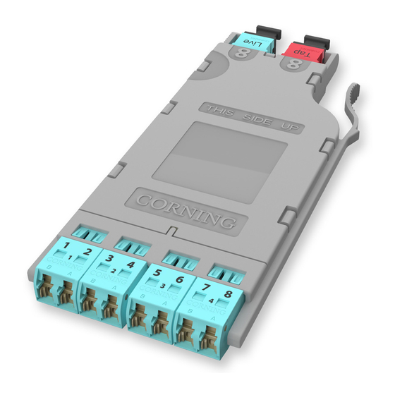
Kontrol Ünitesi CORNING EDGE8 LC-MTP için çevrimiçi göz atın veya pdf Kurulum ve Test indirin. CORNING EDGE8 LC-MTP 8 sayfaları. Tap module
5.
Calculating System Loss Budgets
5.1
This section describes how to calculate the loss budgets of a system using an EDGE8™ Tap
Module. Note that you will need to calculate one loss budget for the LIVE system (Figure 4) and
two different loss budgets for the Tap output (Figure 5 and 6).
Table 1 indicates the system loss values of the system components:
Component
MTP® mated pair loss
LC mated pair loss
Splitter 50/50 (dB)
Splitter 30/70 (dB)
1
Insertion loss specifications when mated to other system components of a like
performance specification
5.2
To calculate the system losses, add the loss values of the components as illustrated in the
examples shown in Figures 4, 5, and 6.
Budget loss for a LIVE multimode system using OM4 fiber and 50 /50 splitters:
LC mated
pair
+
0.15
"Near end"
EDGE8 Tap Module
HPA-0825-EDGE8
STANDARD RECOMMENDED PROCEDURE 003-137-AEN | ISSUE 1 | JANUARy 2017 | PAGE 3 OF 8
Multimode Fiber
optimized 50µm
Loss, max (dB)
Table 1: System Loss Values
MTP
50/50
mated pair
splitter
+
3.70
0.30
OM4
Ultra-bendable
(850 nm)
1
0.30
0.15
3.7
1.80/5.80
0.15 +3.7 + 0.30 +0.25 + 0.10 = 3.70 dB + fiber loss
Note: Fiber loss
depends on length
of system
Single-Mode Fiber
Bend-improved
single-mode
(1310 nm)
Loss, max (dB)
1
0.35
0.25
3.5
5.80/2.10
LC mated
MTP
pair
mated pair
+
0.25
0.10
EDGE8 Module "B"
"Far end"
Figure 4