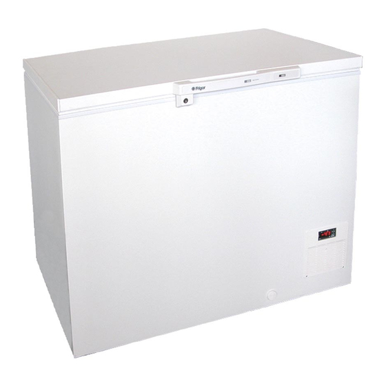
Frigor GLE 10 Kullanıcı Talimatları - Sayfa 8
Dondurucu Frigor GLE 10 için çevrimiçi göz atın veya pdf Kullanıcı Talimatları indirin. Frigor GLE 10 14 sayfaları. Gle series

User Instructions Low Temperature Freezers Model GLE
PARAMETERS
NOTE: the parameters preceded by dots are
in the Hidden Menu.
REGULATION
Hy Differential: (0,1 ÷ 25,5°C / 1÷255 °F) Inter-
vention differential for set point. Compressor
Cut IN is Set Point Plus Differential (Hy). Com-
pressor Cut OUT is when the temperature
reaches the set point.
• LS Minimum set point: (- 50°C÷SET-58°F÷
SET): Sets the minimum acceptable value
for the set point.
• US Maximum set point: (SET÷110°C/ SET÷
230°F). Set the maximum acceptable
value for set point.
Ot Thermostat probe calibration: (-12.0÷
12.0°C; -120÷120°F) allows to adjust possible
offset of the thermostat probe.
• OdS Outputs activation delay at start up:
(0÷255min) This function is enabled at the
initial start up of the instrument and inhibits
any output activation for the period of
time set in the parameter.
AC Anti-short cycle delay: (0÷50 min) mini-
mum interval between the compressor stop
and the following restart.
• CCt Compressor ON time during continu
ous cycle: (0.0÷24.0h; res. 10min) Allows
to set the length of the continuous cycle:
compressor stays on without interruption
for the CCt time. Can be used, for in-
stance, when the room is filled with new
products.
• COn Compressor ON time with faulty
probe: (0÷255 min) time during which
the compressor is active in case of fauly
thermostat probe. With COn=0 compressor
is always OFF.
• COF Compressor OFF time with faulty
probe: (0÷255 min) time during which the
compressor is OFF in case of faulty thermo
stat probe. With COF=0 compressor is
always active.
CH Type of action: CL = cooling; Ht = heating.
DISPLAY
• CF Temperature measurement unit:
°C=Celsius; °F=Fahrenheit. WARNING: When
the measurement unit is changed the SET
point and the values of the parameters Hy,
LS, US, Ot, ALU and ALL have to be checked
and modified if necessary).
User Instructions Low Temperature Freezers Model UNI/LT
Livøvej 22 - 8800 Viborg - Tlf. 86 61 34 11 - www.frigor.dk
8
rES Resolution (for °C): (in = 1°C; dE = 0.1 °C)
allows decimal point display.
DEFROST
IdF Interval between defrost cycles: (0÷120h)
Determines the time interval between the
beginning of two defrost cycles.
MdF (Maximum) length for defrost: (0÷255min)
When P2P = n, (not evaporator probe: timed
defrost) it sets the defrost duration, when P2P
= y (defrost end based on temperature) it sets
the maximum length for defrost.
• dFd Temperature displayed during defrost: (rt
= real temperature; it = temperature at de
frost start; SEt = set point; dEF = "dEF" label)
• dAd MAX display delay after defrost:
(0÷255min). Sets the maximum time
between the end of defrost and the restart
ing of the real room temperature display.
ALARMS
• ALC Temperature alarms configuration:
(Ab; rE) Ab= absolute temperature: alarm
temperature is given by the ALL or ALU
values. rE = temperature alarms are re
ferred to the set point. Temperature
alarm is enabled when the temperature
exceeds the "SET+ALU" or "SET-ALL"
values.
ALU MAXIMUM temperature alarm:
(SET÷110°C; SET÷230°F) when this tempera-
ture is reached the alarm is enabled, after
the "ALd" delay time.
ALL Minimum temperature alarm: (-50.0 ÷
SET°C; -58÷230°F when this temperature is
reached the alarm is enabled, after the
"ALd" delay time.
• ALd Temperature alarm delay: (0÷255 min)
time interval between the detection of an
alarm condition and alarm signalling.
• dAO Exclusion of temperature alarm at
startup: (from 0.0 min to 23.5h) time interval
between the detection of the tempera-
ture alarm condition after instrument
power on and alarm signalling.
SECOND RELAY AND DIGITAL INPUT
• tbA Alarm relay silencing (with oAC=ALr):
(n= silencing disabled: alarm relay stays
on till alarm condition lasts, y =silencing
enabled: alarm relay is switched OFF by
pressing a key during an alarm).
|
8
