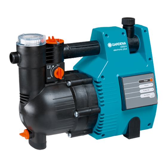
Gardena 1481 Kullanım Talimatları Kılavuzu - Sayfa 7
Su Pompası Gardena 1481 için çevrimiçi göz atın veya pdf Kullanım Talimatları Kılavuzu indirin. Gardena 1481 18 sayfaları. Pressure tank unit electronic plus with dry-running safety
Ayrıca Gardena 1481 için: Kullanım Talimatları Kılavuzu (19 sayfalar)

Before Operation
Setting Up and Filling the Pump
Position the pump at a safe
distance from the liquid to
be pumped
Putting into Operation
Using the pump
for the first time
Electronic Control
Pressure tank units are equipped
with an electronic control unit with
fixed programs.
The electronic control unit is
activated by pulses from the
manometric switch and the flow
recognition of the dry-running
The pump must be positioned on a sturdy, dry surface to ensure
the pump is stable.
V Install the pump at a safe distance (min. 2 m) from the pumping
medium.
The pump must be installed in a location with low air humidity
and sufficient ventilation in the area of the ventilation slots. It
must be at a distance of at least 5 cm from the walls. No dirt
contamination (e.g. sand or earth) may be sucked in through
the ventilation slots.
Filling the pump:
Open the lid of the filter chamber
.
Set the switch to START
.
(➔ the integrated backflow valve is
opened)
Fill the pump completely via the filter
.
chamber with the clean and cold liquid
to be pumped.
Use a suction hose with backflow preventer and fill the hose
.
with water to allow the pump to begin pumping the liquid
fault-free (see section "Inlet Side Connection").
Screw the lid of the filter chamber back on.
.
Set the switch of the backflow valve to START.
.
Slightly open the release points in the delivery pipe
.
(e.g. spray lance, tap)
➔ Air must be allowed to escape during the suction process.
Plug the mains plug into a socket supplying 230 V AC.
.
Warning: The pump starts immediately!
As soon as the pump begins to pump, turn the switch to RUN
(normal operation) ➔ ensures fault-free operation of the pump.
safety feature.
The manometric switch is set at
the factory to a switching pressure
of approx. 2.2 bar. This setting
cannot be changed.
The dry-running safety mech-
anism protects the pump against
damage and controls the time
the pump continues to run
against the closed delivery side.
The LEDs (light emitting diodes)
display the operating status (➔
see "Electronic Control Display").
19
