Gardena 5500/3 Kullanım Talimatları Kılavuzu - Sayfa 3
Su Pompası Gardena 5500/3 için çevrimiçi göz atın veya pdf Kullanım Talimatları Kılavuzu indirin. Gardena 5500/3 9 sayfaları. Submersible pressure pump
Ayrıca Gardena 5500/3 için: Kullanım Talimatları Kılavuzu (14 sayfalar), Kullanım Talimatları Kılavuzu (14 sayfalar), Operatör El Kitabı (9 sayfalar)
3. Initial Operation
Connect hose via the GARDENA
19mm (3/4")- / 16mm (5/8") and 13mm (1/2") hoses can be
Connection System:
connected via the GARDENA Connection System.
Hose diameter
13mm (1/2")
16mm (5/8")
19mm (3/4")
The pump connection component
the manufacturer together with the check valve
v Connect hose via the relevant GARDENA Connection System.
Backflow preventer
The backflow preventer
after the pump has been turned off or taken out of operation.
1
With a parallel connection of more than one hose or connected
devices, the GARDENA 2- / 4-Way Valve (Art. 8193 / 8194) can
be used, which is screwed straight onto the pump connection
ß
piece
1
.
v
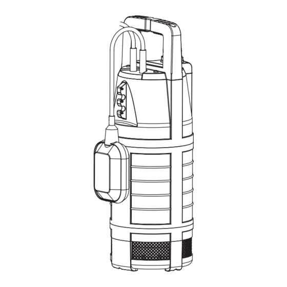
Pump installation:
The pump must always be submerged in the fountain or water
reservoir with the fastening rope
to be primed, the pump must be submerged to the minimum
submersion depth
5
3
So that the filter does not become dirty, the pump should be
fixed at least 30cm above the ground.
4
1. Attach the fastening rope
2. Submerge pump in the fountain or water reservoir via the
fastening rope
3. Secure fastening rope
4. With deep fountains or shafts (from approx. 5m), route the
6
connection cable
Thermal protection switch:
min.
In the event of an overload, the pump is switched off by the
ß
t
built-in thermal motor protection. After sufficient cooling of the
motor, the pump is operational again.
min.
30 cm
12
Pump connection
GARDENA
Pump Connection Set
Art. 1750
GARDENA Tap Connector
Art. (2)902
GARDENA Hose Connector
Art. (2)916
GARDENA
Pump Connection Set
Art. 1752
1
is already pre-installed by
ß
.
v
ß
:
v
ß
v
prevents the hose from running empty
3
provided. For the pump
ß
(see 8. Technical specifications).
t
3
4
to the handle
.
3
.
3
.
5
along the fastening rope
3
with clips.
4. Operation
Automatic operation:
The float switch
water level exceeds the cut-in height and the water is pumped
out. The float switch
the water level falls below the cut-out height.
v During automatic operation, ensure that the float
switch
5
Adjusting the Cut-in and Cut-out Height:
The cable length between the float switch
lock
7
must always be at least 10cm.
1. Press the cable of the float switch
float switch lock
Do not select a cable length that is too long or short to ensure
7
6
that the float switch can turn on and off properly.
2. Plug the mains plug of the connection cable
socket.
• The higher the opening of the float switch lock
the cut-in and cut-out height.
• The shorter the length of cable between the float switch
and the float switch lock
higher the cut-out height.
Manual operation:
The pump remains in constant operation when the float switch is
attached facing upwards so that the cable is pointing downwards.
v Attach the float switch
downward.
The residual water height of approx. 25mm is only reached
during manual operation since the float switch turns off
the pump during automatic operation before this water level
is reached.
5. Putting into Storage
Frost-free storage:
The storage location must not be accessible to children.
v Store the pump away from frost before the first frost sets in.
The product must not be added to normal household waste.
Disposal:
(in accordance with
It must be disposed of in line with local environmental regulations.
RL2002/96/EC)
6
turns the pump on automatically when the
6
turns the pump off again as soon as
6
can move freely.
6
and the float switch
6
into an opening in the
7
.
5
into a mains
7
, the higher
7
, the lower the cut-in height and the
6
to the top so that the cable points
6
13