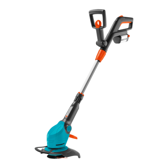
Gardena EasyCut Li-18/23 R Kullanım Talimatları Kılavuzu - Sayfa 5
Düzeltici Gardena EasyCut Li-18/23 R için çevrimiçi göz atın veya pdf Kullanım Talimatları Kılavuzu indirin. Gardena EasyCut Li-18/23 R 17 sayfaları. Accu turbotrimmer
Ayrıca Gardena EasyCut Li-18/23 R için: Kullanım Talimatları Kılavuzu (16 sayfalar), Kullanım Talimatları Kılavuzu (17 sayfalar), Kullanım Talimatları Kılavuzu (18 sayfalar), Operatör El Kitabı (11 sayfalar)

3. Assembly
Assembling the trimmer:
o
h
ß
R
j
g
t
2
e
w
ö
3
k
ß
ß
A2
A1
CAUTION!
The handle may only be assembled if the cable
between the handle and the shaft is in a perfect
condition. The handle may not be assembled if
the cable is damaged. Contact GARDENA customer
service in such a case.
CAUTION!
The trimmer may only be operated provided that the
protective cover
1
1. Carefully remove the handle
the packaging. In doing so, no stress may be exerted upon the
cable.
2. Ensure that the threaded collar
(padlock symbol open).
3. Slide the handle
In doing so, the cable may not become twisted or jammed.
4. By pulling on the handle
the shaft
cannot be separated.
5. Close the threaded collar
6. Pull the lock
both of the snap-fits
and, with the grooves
holder
7. Only for art. 9825: Place both halves of the impeller
the lower groove
0
audibly engage.
l
8. From the front, push the plant guard
groove
the impeller
the kink pointing upwards).
9. Place the protective cover
10. Turn the protective cover
trimmer head entirely (the two arrows
from each other).
11. Rotate the protective cover
engages.
12. Slightly widen the magazine
the shaft
13. Slide up to 6 plastic blades
blades clamp into place.
20 plastic blades and a magazine for spare blades are included in
q
the delivery. Up to 6 spare blades can be stored in the magazine.
For information regarding the assembly of the blade into
the blade holders, please consult 8. Troubleshooting
"Replacing the plastic blade".
q
is assembled.
1
1
onto the shaft
1
, check whether it is firmly fixed to
2
. Once assembled, the handle
t
(padlock symbol closed).
o
belonging to the additional handle
g
belonging to the additional handle
ß
pointing forwards, snap them into the
R
j
.
l
of the trimmer head
0
of the trimmer head
k
can rotate freely (i.e. insert the bow with
q
q
until it can be pushed over the
q
w
2
.
e
together with the shaft
t
is in an open position
2
until it audibly engages.
1
and shaft
h
3
and close until they
ö
into the upper
3
. In doing so, ensure that
on top of the trimmer head
ß
ß
,
are directly across
A1
A2
anti-clockwise until it audibly
at the open point and slide onto
w
into the magazine
until the
2
from
2
, push in
h
k
around
3
.
17
