Garmin CATALYST Kullanıcı El Kitabı - Sayfa 7
Araç Navigasyon sistemi Garmin CATALYST için çevrimiçi göz atın veya pdf Kullanıcı El Kitabı indirin. Garmin CATALYST 18 sayfaları. Driving performance optimizer
Ayrıca Garmin CATALYST için: Kullanıcı El Kitabı (34 sayfalar)
The cable is designed to be routed out of sight. To hide the
cable, route it behind the vehicle trim along the windscreen,
doorframe or dashboard.
3
If necessary, use the included adhesive cable clips to secure
the camera cable to the frame of your vehicle.
4
Connect the camera cable to the USB port on the magnetic
mount.
Connecting the Device to the Magnetic
Mount
The magnetic mount supplies power to the Garmin Catalyst
device. Before you use your device on battery power, you
should charge it.
Place the back of the device onto the magnetic mount.
Installing the Screw-Down Ball Mount on the
Dashboard
Before you can attach the screw-down ball mount to your
dashboard, you must select a suitable location on the dashboard
and purchase the appropriate hardware for your mounting
surface.
It is your responsibility to ensure the mounting location complies
with all applicable laws and ordinances, and does not block your
view of the road during the safe operation of your vehicle.
Avoid wires, gauges, air bags, air bag covers, heating,
ventilation, and air conditioning and other items when drilling
pilot holes and attaching the mount to the vehicle. Garmin is not
responsible for any damages or consequences arising from the
installation.
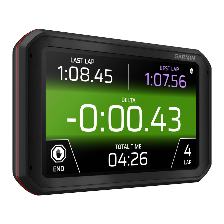
Device Overview
WARNING
NOTICE
Garmin recommends professional installation of the screw-down
ball mount.
The device includes an optional four-hole AMPS pattern mount
that you can secure to the dash board in place of the suction
cup. This can be useful if you are unable to mount the device on
a windscreen.
1
Place the mount on the selected location.
2
Using the mount as a template, mark the four screw locations
.
3
If necessary for your mounting surface, drill pilot holes.
NOTE: Do not drill through the mount.
4
Securely fasten the mount to the surface using M4 or no. 8
screws suitable for your mounting surface.
™
Microphone
Volume control
Power button
Micro USB power and data port
Auxiliary memory card slot (for additional memory)
3.5 mm audio jack
Magnetic mount interface with 14-pin connector
NOTICE
Device Overview
3