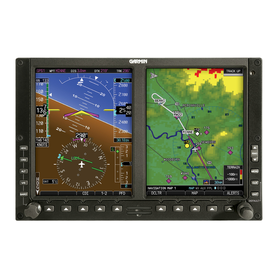
Garmin G500 Manuel - Sayfa 12
Aviyonik Ekran Garmin G500 için çevrimiçi göz atın veya pdf Manuel indirin. Garmin G500 40 sayfaları. Primary flight and multifuction display system
Ayrıca Garmin G500 için: Hızlı Referans (2 sayfalar), Talimatlar Kılavuzu (14 sayfalar)

1.6
Audio Panel
The G500 PFD/MFD system should be interfaced into the aircraft audio panel to
provide aural altering generated by the G500 (required for SVT installations).
1.7
Traffic and Weather Systems
The G500 PFD/MFD system supports TIS traffic via the Garmin GTX Series
Mode-S Transponders. The system also supports TAS/TCAS/TIS traffic from
various active traffic awareness systems. The information from these systems is
available and controllable on the MFD.
The G500 PFD/MFD system supports XM datalink weather via the Garmin
GDL69 and GDL69A receivers. If an optional XM datalink receiver is installed,
the pilot will be able to access graphical and text weather products on the MFD
and control the audio entertainment data from the MFD while listening via an
appropriately installed audio panel.
Datalink weather is also available via the Garmin GSR 56 Iridium Transceiver.
The control and display of Iridium satellite weather on the MFD is similar to
XM weather.
Control and display of various airborne weather radars is optionally available on
the MFD. The G500 supports Garmin GWX weather radar, as well as certain
rd
3
-party weather radars.
1.8
Video sources
The G500 Avionics Display System can display images from up to 2 video
inputs. Video images are displayed on the MFD. The G500 does not provide a
means to control the video source; however the digital images from the video
source can be adjusted using the G500.
1.9
Radar Altimeter
The G500 supports the display of radar altitude on the PFD from supported
radar altimeters.
1.10 High Speed Data Bus Interface
Some Garmin equipment connected to the G500 system utilizes the High Speed
Data Bus (HSDB) interface. HSDB is similar to an Ethernet bus and provides a
high-speed interface between Garmin avionics. Like Ethernet, data between two
units may be passed through intermediate "hub" units. Interfaced equipment
that uses HSDB includes the GTN 6XX/7XX navigators, GDL 69 datalink
receiver, GWX 68, and GTS 8XX traffic systems.
The HSDB interfaces are installed to so that maximum data path redundancy is
achieved. However, depending on the number of HSDB units installed, failure
of one HSDB unit may result in loss of data on the G500 from "downstream"
HSDB units. Any loss of data will be annunciated on the G500.
AFMS, GARMIN G500 PFD/MFD SYSTEM
FAA APPROVED
190-01102-01 Rev. 9
Page 12 of 40
