Garmin GTX 327 Pilot El Kitabı - Sayfa 6
Deniz Telsizi Garmin GTX 327 için çevrimiçi göz atın veya pdf Pilot El Kitabı indirin. Garmin GTX 327 8 sayfaları. Mode a/c transponder
Ayrıca Garmin GTX 327 için: Pilot El Kitabı (8 sayfalar), Pilot El Kitabı (8 sayfalar), Pilot El Kitabı (8 sayfalar), Pilot El Kitabı (4 sayfalar)

Function Display
NOTE: Transponder options are normally set at time of installation. For
changes to the GTX 327 parameters, contact your Garmin authorized
service center.
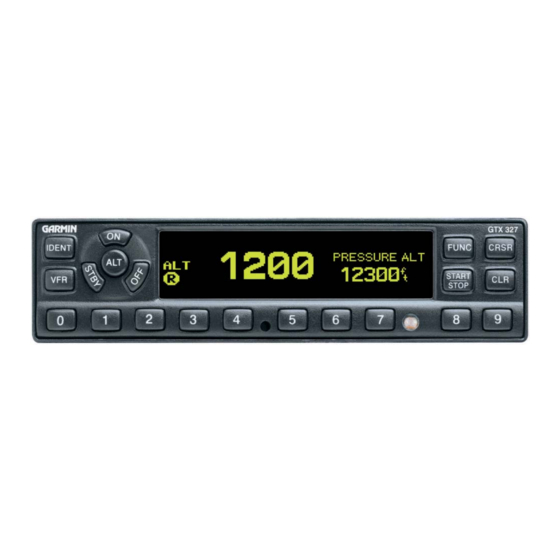
Altitude Trend Indicator
When the PRESSURE ALT page is displayed, an arrow may be displayed to the right of
the altitude, indicating that the altitude is increasing or decreasing. One of two sizes of arrows
may be displayed depending on the vertical speed rate. The sensitivity of these arrows is set
during transponder installation.
Automatic ALT/STBY Mode Switching
If the GTX 327 is configured with Automated Airborne Determination, ALT mode
selection occurs when lift-off is sensed. When the aircraft is on the ground, the transponder
automatically selects and displays STBY. The transponder does not respond to ATCRBS
interrogations when STBY is annunciated. When a delay time is set (dependent upon
installation configuration), the GTX 327 waits the specified length of time after landing before
changing to STBY mode.
ADS-B Control (GDL 90)
Automatic Dependent Surveillance-Broadcast (ADS-B) technology improves situational
awareness and flight safety. With ADS-B capabilities, position, velocity, and heading
information are automatically transmitted to other aircraft and ground stations. The GTX 327
provides mode control for the optional GDL 90 Universal Access Transceiver (UAT) datalink.
The GDL 90 provides ADS-B capabilities.
PRESSURE ALT: Displays the altitude data supplied to the GTX 327 in feet,
hundreds of feet (i.e., flight level), or meters, dependent upon installation
configuration.
FLIGHT TIME: Displays the Flight Time, configured during installation
as MANUAL, CLEAR, or ACCUMULATE (see Timer Operation for details).
Timer is controlled by the START/STOP and CLR keys when configured as
Manual.
COUNT UP TIMER: Controlled by START/STOP and CLR keys.
COUNT DOWN TIMER: Controlled by START/STOP, CLR, and CRSR
keys. The initial Count Down time is entered with the 0 – 9 keys.
CONTRAST: This page is only displayed if manual contrast mode is
selected during installation configuration. Contrast is controlled by the 8
and 9 keys.
DISPLAY: This page is only displayed if manual backlighting mode is
selected.during installation configuration. Backlighting is controlled by the 8
and 9 keys.
