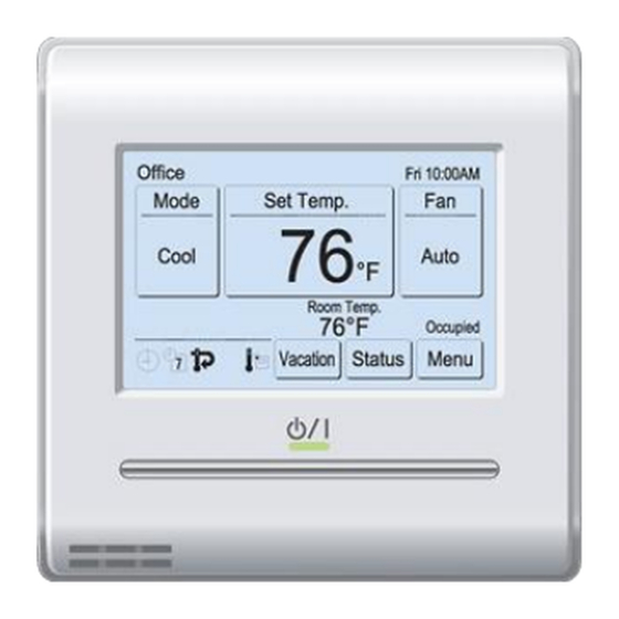
Fujitsu UTY-RNRUZ2 Kurulum Kılavuzu - Sayfa 2
Klima Fujitsu UTY-RNRUZ2 için çevrimiçi göz atın veya pdf Kurulum Kılavuzu indirin. Fujitsu UTY-RNRUZ2 11 sayfaları. Remote controller (wired type)
Ayrıca Fujitsu UTY-RNRUZ2 için: Kullanım Kılavuzu (26 sayfalar)

4. S ELECTING AN INSTALLATION
LOCATION
4.1. Dimensions and Name of parts
Remote controller unit
Hole: 3/8 × 3/16
(9 × 4.5)
4-3/4 (120)
13/16 (20.4)
Hole: 1/4 × 3/16
(a) (b) (c) (d)
(6 × 4.5)
(a) Room temperature sensor (inside)
(b) Operation (Ocupied/Unoccupied)
button:
It is possible to operate only while
displaying the Monitor Mode
screen.
(c) LED lamp (Operation indicator)
(d) Touch panel display
Monitor mode screen
The home screen of this unit. Except
for in the following cases, the screen
will return to this screen if there is no
operation for over 10 min. (Unsaved
settings will be cancelled.)
• In Emergency Stop.
• In Transferring data.
• In checking the indoor unit position
• In Function Setting
• In Vacation
(a) R.C. Group name: Refer to 6.3.4.
(b) Clock: Refer to 6.2.4.
(c) Mode: Set the operation mode. Refer to operating manual.
(d) Set Temp.: Set the operating temperature. Refer to operating manual.
(e) Fan: Set the fun speed. Refer to operating manual.
(f) Away: When "Away" is enabled, the start temperature of "Away" opera-
tion is displayed when unoccupied. When "away" is operating, "Away
Operation" is displayed. Refer to operating manual.
(g) Room temperature: Refer to 4.2. and 6.3.5.
(h) Override: Displayed while the following functions are operating:
• Auto Off Timer
• Set Temp. Auto Return
Refer to operating manual.
(i) Occupied state: "Occupied" or "Unoccupied" is displayed according to
the operation of Operation button or schedule setting.
In the following cases, the operation button needs to be pressed twice:
• When stopping the operating indoor unit while "Unoccupied" is
displayed, press the operation button once to set to "Occupied" and
press it again to set to "Unoccupied". Then the indoor unit stops.
• When operating the stopped indoor unit while "Occupied" is displayed,
press the operation button once to set to "Unoccupied" and press it
again to set to "Occupied". Then the indoor unit operates.
In the following cases, the occupied state does not switch to "Occupied"
even if the indoor unit starts operation:
• Anti freeze operation
• Away operation
• Optimum start operation
En-2
Unit: in (mm)
1-3/16 (30) 1-5/16 (33)
7/8
(23)
Hole: 1/2 × 3/16
(12.5 × 4.5)
All Fujitsu General products are
manufactured to metric units
and tolerances. United States
customary units are provided for
reference only.
In cases where exact
dimensions and tolerances are
required, always refer to metric
units.
(a)
(m)
(d)
(n)
(b)
Office
Fri 10:00AM
Mode
Set Temp.
Fan
(n)
80°F
Cool
Custom
Auto
(c)
Auto
74°F
Heat
(f)
Room Temp.
Cool
84°F
Override
Away
76°F
(n)
Heat
68°F
Occupied
Vacation
Status
Menu
(n)
(l)
(k)
(j)
(j) Menu: Set the various settings.
(k) Status: Check the status of indoor unit and error.
(l) Vacation: When this is touched, the schedule is disabled and the
indoor unit remains unoccupied. "Vacation" is displayed only when a
schedule is set. Refer to operating manual.
(m) "Custom Auto Mode" or "Away" does not work.
Verify the following settings:
• R.C. Sensor Setting: Refer to 6.3.5.
• Master Indoor Unit Setting: Refer to 6.3.6.
When the remote controller that uses a sensor is changed in the mas-
ter indoor unit or R.C. Group, change the operation mode or disable
"Away".
(n) Status icons: Refer to operating manual.
For the screen display other than Chinese, this product uses a Bitmap
font made and developed by Ricoh Company, Ltd.
4.2. S etting the room temperature detection
location
As the temperature sensor of remote controller detects the temperature
near the wall, when there is a certain difference between the room
temperature and the wall temperature, the sensor will not detect the
room temperature correctly sometimes. Especially when the outer side
of the wall on which the sensor is positioned is exposed to the open air,
it is recommended to use the temperature sensor of the indoor unit to
detect the room temperature when the indoor and outdoor temperature
difference is significant.
The detection location of the room tempera-
ture can be selected from the following 2
methods. Choose the detection location that
is best for the installation location.
The temperature sensor of the indoor unit or
the remote controller can be used to detect
(e)
the room temperature.
(g)
(h)
(i)
When the remote controller is not used, the following functions cannot
be used.
• [Custom Auto] of the operation modes: Refer to operating manual.
• [Away Setting]: Refer to operating manual.
4.3. Installation space
• Do not embed this remote controller in a wall.
• Recommendation installation height of the remote controller is 55 in (1.4
m) (from the floor surface to the bottom of the remote controller).
• Even when you install a remote
controller to one of a switch box
and the surface of a wall, secure
the space shown in following
figure. When there is insufficient
space, there may be remote con-
troller sensor misdetections and
remote controller removal may be
difficult.
* Please secure enough space where a flat-blade screwdriver to take off a
case can be inserted.
CAUTION
A sensor of the indoor
unit (inside)
A sensor of the remote
controller (inside)
2 (30) or
more
2 (30)
or more
9 (220)
or more*
Unit: in (mm)
2 (30)
or more
