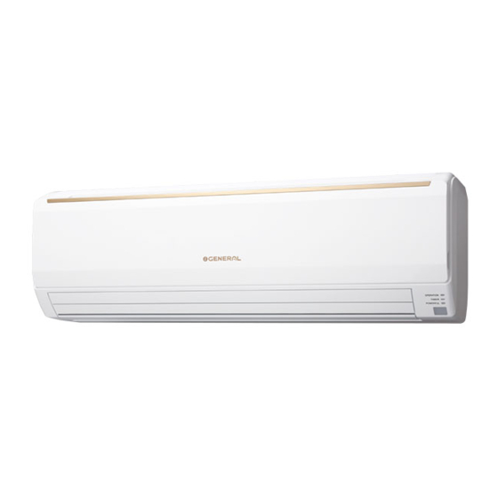
Fujitsu Wall Mounted Type Kurulum Kılavuzu - Sayfa 6
Klima Fujitsu Wall Mounted Type için çevrimiçi göz atın veya pdf Kurulum Kılavuzu indirin. Fujitsu Wall Mounted Type 18 sayfaları. Air conditioner outdoor unit, wall mounted type, r410a

6.3. Cutting the hole in the wall for the connecting piping
(1) Cut a 80 mm (3-5/32 in.) diameter hole in the wall at the
position shown in the fi gure.
(2) When cutting the wall hole at the inside of the wall hook
bracket, cut the hole to a point of intersection of center marks.
When cutting the wall hole at the outside of the wall hook
bracket, cut the hole at a point of 10 mm (13/32 in.) below.
(3) Cut the hole so that the outside end is lower (5 to 10 mm
(3/16 to 13/32 in.)) than the inside end.
(4) Always align the center of the wall hole. If misaligned, wa-
ter leakage will occur.
(5) Cut the wall pipe to match the wall thickness, stick it into
the wall cap, fasten the cap with vinyl tape, and stick the
pipe through the hole.
(6) For left piping and right piping, cut the hole a little lower so
that drain water will fl ow freely.
Wall hook bracket
10 mm (13/32 in.)
80 mm (3-5/32 in.)
hole
or more lower
Fasten with
vinyl tape
Wall pipe*
Wall cap*
(Inside)
If the wall pipe is not used, the cable interconnecting
the indoor unit(s) and outdoor unit or branch box may
touch metal and cause electric discharge.
] 1
6.4. Installing the wall hook bracket
(1) Install the wall hook bracket so that it is correctly posi-
tioned horizontally and vertically. If the wall hook bracket is
tiled, water will drip to the fl oor.
(2) Install the wall hook bracket so that it is strong enough to
support the weight of the unit.
● Fasten the wall hook bracket to the wall with 6 or more
screws through the holes near the outer edge of the bracket.
● Check that there is no rattle at the wall hook bracket.
Wall hook bracket
Install the wall hook bracket level, both horizontally
and vertically.
En-6
Centering marks
10 mm (13/32 in.)
or more lower
5 to 10 mm (3/16 to 13/32 in.)
Wall
(Outside)
*Field supplied
WARNING
Tapping screw
(size: large; quantity: 8)
CAUTION
6.5. Forming the drain hose and pipe
[Rear piping, Right piping, Bottom piping]
• Install the indoor unit piping in the direction of the wall hole
and bind the drain hose and pipe together with vinyl tape.
• Install the piping so that the drain hose is at the bottom.
• Wrap the pipes of the indoor unit that are visible from the
outside with decorative tape.
[For Left rear piping, Left piping]
Interchange the drain cap and the drain hose.
CAUTION
• Insert drain hose and drain cap securely. Drain
should slope down to avoid water leakage.
• When inserting, be sure not to attach any material
besides water. If any other material is attached, it will
cause deterioration and water leakage.
• After removing drain hose, be sure not to forget
mounting drain cap.
• Be sure to fi x the drain hose with tape to the bottom of piping.
• Prevent drain water freezing under low temperature
environment.
When installing indoor unit's drain hose outdoors, neces-
sary measure for frost protection should be taken to pre-
vent drain water freezing.
Under low temperature environment (when outdoor tem-
perature under 32 °F), after cooling operation is executed,
water in the drain hose could be frozen.
Once drain water is frozen, the drain hose will be blocked
and water leakage may result at the indoor unit.
Right piping
Indoor unit drain hose
Bottom
(bottom)
piping
Indoor unit
drain hose
Drain cap
CAUTION
Insert the drain hose and drain cap into the drain port,
making sure that it comes in contact with the back of
the drain port, and then mount it. If the drain hose is
not connected properly, leaking will occur.
• Attach the Drain hose insulation to the drain hose.
Drain hose
Bind with vinyl tape
Pipe (top)
Rear piping
For left outlet piping, cut
off the piping outlet cutting
groove with a hacksaw.
Remove the drain cap by
pulling at the projection
at the end of the cap with
pliers, etc.
Drain hose insulation
