Fujitsu MB96300 series Kullanıcı Kılavuzu - Sayfa 8
Anakart Fujitsu MB96300 series için çevrimiçi göz atın veya pdf Kullanıcı Kılavuzu indirin. Fujitsu MB96300 series 36 sayfaları. Mb96300 series

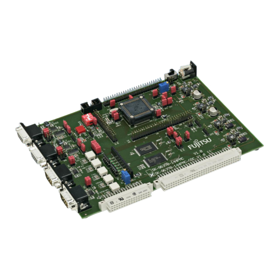
SK-96370-144PMC-GDC User Guide
Chapter 1 Overview
1.3 General Description
2
The SK-96370-144PMC-GDC supports the F
MC-16FX microcontrollers of MB96370 Series
with LQFP144-M08 (PMC) package.
It can be used as a stand-alone evaluation board or as a target board for the emulator
debugger.
1.3.1 MCU Clocks
The board is supplied with a socketed 4 MHz crystal as main oscillation source. Using the
internal PLL of the IC, internal clock rates up to 56 MHz can be achieved.
1.3.2 RS-232 and LIN
Two separate RS232 transceivers and two single-wire LIN-transceivers (TLE7259) are
available to connect two out of three on-chip UARTs to 9-pin D-Sub connectors (X5, X9).
The transceivers generate the adequate RS232 levels for the receive (RXD) and transmit
(TXD) and LIN bus lines. In RS232 mode, either the DTR line or the RTS line can be
selected with jumpers (JP23 and JP38) to generate a system reset. The RTS signal can be
shortcut to CTS using the jumpers JP19 and JP36. Each of the four D-Sub connectors can
be configured as RS232 or LIN. The LIN Vs line can be powered by the unregulated supply
input of the board, so no additional supply is needed (JP28 and JP42).
All transceivers are fully 3.3V IO compatible to enable low voltage applications.
In-circuit programming (asynchronous) can be done via LIN-UART 0 and 2 (X5, X9).
1.3.3 CAN Bus
Two high-speed CAN transceivers (TLE6250GV33) can be connected to the CAN interfaces
of the MCU to allow easy connection to CAN networks.
All transceivers are fully 3.3V IO compatible to enable low voltage applications.
1.3.4 MCU Pins
All pins of the microcontroller except the oscillator pins X0/X1 and X0A/X1A are connected
to edge connectors and are directly available to the user.
1.3.5 Power Supply
The on-board switching mode voltage regulators allow the user to connect an unregulated
DC input voltage of +9V to +15V, and supplies all voltages needed by the board and an
optional graphic sub-board. The regulators are rated with 3A (5V and 3.3V) resp. 1.5A (2.5V,
1.8V) and are thermally protected against overload.
1.3.6 User Buttons
There are six push button switches on the board, which can be connected to input ports of
the microcontroller. This allows the user to evaluate external Interrupts, external timer trigger
or Input Capture functions as well as simple input polling. One button is reserved as 'Reset'-
button for the microcontroller, controlled by the supply monitor IC.
1.3.7 User LEDs and optional LCD
Eight user LEDs are connected to Port 09 and grounded by two 1k resistor networks (RN1,
RN2). If these LEDs are not required, these resistor networks can be removed to disconnect
the LEDs and to free the I/O port.
FMEMCU-UG-960014-10
- 8 -
© Fujitsu Microelectronics Europe GmbH
