Aqua Computer AQUASTREAM XT USB Kullanım ve Kurulum Kılavuzu - Sayfa 6
Su Pompası Aqua Computer AQUASTREAM XT USB için çevrimiçi göz atın veya pdf Kullanım ve Kurulum Kılavuzu indirin. Aqua Computer AQUASTREAM XT USB 20 sayfaları.
Ayrıca Aqua Computer AQUASTREAM XT USB için: Kullanıcı ve Kullanım Kılavuzu (16 sayfalar)

AQUASTREAM XT
completely into the pump housing and is not visible if the adapter is correctly in-
stalled. Excessive force may damage the pump!
Should you be using a plug-on reservoir with the pump (e. g. aquainlet), remove
the silver suction grille and mount the tank directly onto the water inlet port of the
aquastream XT pump. In this case no connecting adapter is to be installed into the
inlet port.
7. 7. 7. 7. Electrical connections
Electrical connections
Electrical connections
Electrical connections
7.1. Connection panel of the aquastream XT pump
7.1. Connection panel of the aquastream XT pump
7.1. Connection panel of the aquastream XT pump
7.1. Connection panel of the aquastream XT pump
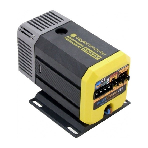
The pump controller board is integrated on
the rear side of the pump. The controller
board features connectors for power supply,
fan, speed signal, aquabus interface or flow
sensor, external temperature sensor and
USB interface. Please note that depending
on the version of the pump, some connect-
ors may be without function.
ATTENTION: Completely turn off your
power supply or disconnect the mains
power cord from the wall outlet before connecting or disconnecting any cables
to/from the device!
7.2. Connector "power"
7.2. Connector "power"
7.2. Connector "power"
7.2. Connector "power"
Connect a power plug of your PC's power supply unit to this connector. Do not
use excessive force but double check the polarity of the plug if you are having
trouble to connect.
Pin assignment:
Pin 1: +12 V
Pin 2: GND
Pin 3: GND
Pin 4: not connected
7.3. Connector "USB"
7.3. Connector "USB"
7.3. Connector "USB"
7.3. Connector "USB"
This connector is used for USB communication to the PC and for power supply.
Connect to an internal USB header of your motherboard. Take special care to
make sure the pin alignment matches your motherboard!
Pin assignment:
Pin 1: not connected
Pin 2: GND(black)
Pin 3: D+ (green)
Pin 4: D-
Pin 5: +5 V(red)
- 6 -
(white)
Aqua Computer GmbH & Co. KG
Gelliehäuser Str. 1, 37130 Gleichen
aqua
computer
© 2007-2013
