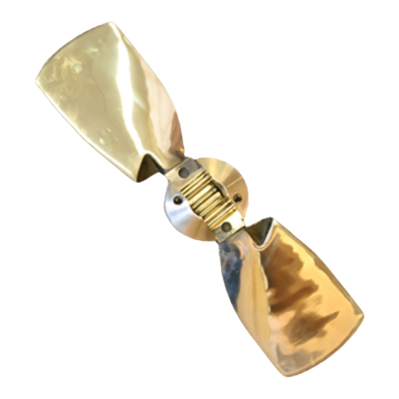
AB Marine Gori Kurulum Talimatları Kılavuzu - Sayfa 3
Denizcilik Ekipmanları AB Marine Gori için çevrimiçi göz atın veya pdf Kurulum Talimatları Kılavuzu indirin. AB Marine Gori 8 sayfaları. 2-blade saildrive propeller

[Gori 2-Blade Saildrive Propeller Installation and Maintenance Instructions, 6/21/2022]
The propeller is delivered assembled. This ensures that at the factory the propeller has been checked and
balanced before shipping.
1. Take the propeller apart – Remove the two (7&8) M8 Allen screws per blade pin. Push blade pins (3)
out with a wooden dowl to not damage the pin end. The blades, pins and hub are all marked (#1 &
#2) so as to re-assemble in the correct balanced location. Note: here are two (2) Allen screws per
blade pin.
2. Ensure that the Saildrive spacer supplied with the saildrive unit is in place at the forward end of the
output shaft. The forward face of the saildrive propeller hub presses against this saildrive spacer to
keep the retaining cap/blade housing clear of the saildrive leg zinc.
3. Lightly smear spline grooves and shaft with waterproof lithium anti-corrosion lubricant as specified by
saildrive manufacturer.
4. Slide the hub (1) onto the shaft spline. Check that the supplied shaft nut (5), threads on to the end of
the output shaft
5. Apply locking glue (Loctite 243) to the shaft and nut threads and install the GORI supplied nut (5) and
tighten/torque (see above torque settings) the nut. To tighten the nut to the specified torque for your
saildrive model, move the shift lever to Ahead and hold the crankshaft V-Pulley clamp nut with a
wrench to stop the propeller shaft from rotating. Put a dab on the shaft thread after the nut is torqued
in place. This is required by Loctite. See above socket sizes.
The supplied Loctite 243 locking glue is "Blue" and is for disassemble of parts with
hand tools. Loctite "Red" is permanent and requires heat to undo (450°F for 5
minutes). Applying locking glue correctly is important. The surfaces must be clean
and degreased. Glue needs to be put in the hole as well as threads for blind holes such
as with the Locking bolt.
It is very important to always use the Gori supplied propeller nut for the installation.
An incorrect nut can lead to loss of the propeller, part of the propeller or cause an
electrical connection between the propeller and the saildrive.
6. Install the two (2) nut locking M6x6 setscrews into the two threaded holes in the nut aft face (supplied
in parts bag) with Loctite applied to threads. Tighten using 3mm Allen wrench. On older nut versions
setscrew holes may not be present.
7. Smear Loctite 243 on the thread of the nut-locking bolt (9). Place the washer (4) into the shaft nut
and then screw in the nut-locking bolt (9) using a 5mm Allen key (19). Tighten Locking Bolt to 9-10
ft/lbs(15NM) of torque.
8. On older saildrive models there may be a hole drilled through the shaft thread at the end of the shaft.
If so tighten the nut to required torque and then align the shaft tit end hole with the closest hole on
the shaft nut (5) and insert the cotter pin (6) and bend over.
On newer GORI models (2020+) the shaft nut has two(2) M4 locking setscrews threaded into the
encapsulated washer part of the nut. Apply Locking glue to the two(2) set screws & tighten them into
the aft face of the prop hub as a double locking method for securing the nut.
Installing the Propeller
Distributed By
AB Marine, Inc ▪ 747 Aquidneck Ave ▪ Middletown ▪ RI 02842
Tel: 401-847-7960 ▪ Fax: 401-849-0631
Email:
▪ Website: www.AB-Marine.com
