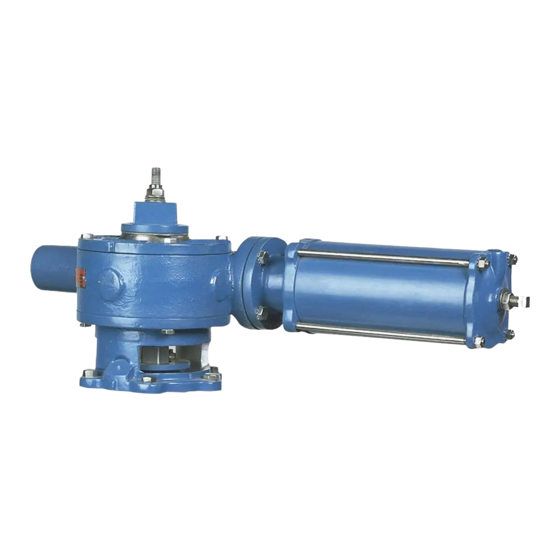
Changing Mounting Positions
8. Scribe corresponding lines on the actuator cover and housing, then remove the cover screws
and cover from the top of the actuator.
9. Mark which teeth of the rack and gear are engaged and lift the gear sector out of the actuator.
This valve is a pressure vessel. Removing the bonnet bolts before relieving pipeline pressure
can result in personal injury or equipment damage. Always relieve pipeline pressure before
removing the actuator.
10. Remove the screws fastening the adapter to the adaptor plate (2"- 4" valves) or to the valve
bonnet (5" - 16" valves).
11. Take out the four screws fastening the actuator housing to the adapter.
12. Rotate the adapter on the valve, and the actuator on the adapter until the holes line up and
the actuator is in the desired position. Replace all of the screws.
13. Find the tooth that was marked on the gear sector and count over clockwise four teeth on the
size 6 actuator, and five teeth on the size 12 actuator. This is the tooth that will engage with
the marked tooth on the rack. Install the gear sector using the new tooth engagement, and be
sure the gear sector fits on the plug stem properly.
14. Set a new cover gasket on the housing, then install and fasten the top cover on the housing;
make sure the scribe marks line up.
15. Slide the bearing washer down the plug stud.
16. Screw the plug adjusting nut down the plug stud until it touches the bearing washer.
17. Turn the plug adjusting nut clockwise until there is .010" clearance between the plug face and
the body seat. (If the valve is used with paper stock, the clearance should be .030".
Note:
The holes in the bearing washer must line up with the tapped holes in the top of the
gear sector.
18. Slide the pointer down the plug stud so that it rests on top of the bearing washer; the pointer
should point to the correct valve position. Fasten the pointer to the gear sector with the two
shorter socket head screws.
19. Slide the wrenching square down the plug stud so that it rests on top of the pointer. Fasten the
wrenching square to the gear sector with the four remaining socket head screws.
20. Screw the lock nut down the stud until it contacts the wrenching square and tighten to lock the
assembly into place.
21. Connect the supply pressure tubing to the cylinder.
22. Check the stop settings and readjust if necessary. The correct adjustment procedure is
described in the STOP ADJUSTMENT section of this instruction.
23. Reconnect power to the actuator.
24. Pipeline flow may now be restored.
July 2016
Cylinder Operated G-Series Actuator
(Continued)
Page 13
DeZURIK
D10191

