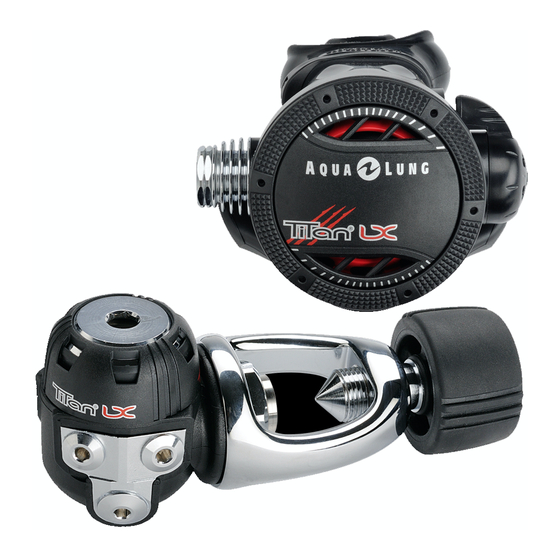
Aqua Lung Titan Bakım Kılavuzu - Sayfa 11
Kontrolör Aqua Lung Titan için çevrimiçi göz atın veya pdf Bakım Kılavuzu indirin. Aqua Lung Titan 20 sayfaları. Second stage
Ayrıca Aqua Lung Titan için: Teknik Bülten (4 sayfalar), Servis Kılavuzu (19 sayfalar)

Calypso/Titan Second Stage Service Manual
Make sure that the cover is seated evenly all the way around
NOTE:
If your facility is equipped with a test bench,
perform the tests before installing the mouthpiece. General
instructions for performing bench tests are located in the
next section, "Final Testing."
26.
If equipped with a
Comfo-bite mouthpiece,
make sure the 'bridge'
of the mouthpiece (6) is
facing upward. Stretch
the mouthpiece over the
second-stage mouth-
piece boss. At the base
of the mouthpiece is a
groove for the reusable
clamp (5). Wrap the clamp around the mouthpiece so that
the cam buckle points toward the hose and the cam lever
points downward. Mate the cam lever hook with the hook
on the free end of the clamp. Press down on the cam lever
until the buckle snaps closed.
27.
Attach the MP hose (25)
to the second stage.
Using an 11/16
(17mm)
"
crow's foot, apply a
torque of 40 (± 3) in. lbs.
NOTE:
Before performing the following procedure, refer
to Table 5, titled Test Bench Specifications – Calypso 2
to Table 5, titled Test Bench Specifications – Calypso 2
to Table 5, titled Test Bench Specifications – Calypso 2
Stage.
NOTE:
If an accurately calibrated airflow test bench is not
available, proceed to the Subjective Tuning Procedures
provided on the following page.
This ends reassembly of the
Calypso/Titan Second Stage
FINAL TESTING PROCEDURES
Second Stage Air Flow Test
1.
Connect the first stage regulator to a calibrated test bench
and pressurize the system to 3000 (±100) psi.
2.
Place the second stage mouthpiece over the mouthpiece
adapter. Slowly turn the flowmeter control knob until
the flow reaches a minimum of 14 SCFM (400 liters per
minute). The reading on the Magnahelic gauge (inhalation
/ exhalation effort gauge) should indicate no more than
+6.O" H2O. If the reading exceeds +6.0" H2O, refer to Table
1 - Troubleshooting for corrective guidelines and specific
procedures.
Second Stage Opening Effort Test
1.
Turn the flowmeter control knob shut, and then slowly
reopen while watching both the Magnahelic gauge and the
intermediate pressure gauge.
2.
When the intermediate pressure gauge begins to drop
below the intermediate pressure "lockup," the Magnahelic
gauge should indicate an opening effort of +0.8 to +1.4 inch
of H2O for a primary second stage and +1.2 to +1.8 inch of
H2O for the octopus. If the opening effort is not within this
range, refer to Table 1 - Troubleshooting.
Second Stage Purge Flow Test
1.
Turn off the flowmeter control knob. Next, while the second
stage is still mounted on the mouthpiece adapter, watch
the flowmeter gauge and depress the purge button until
the second stage valve is completely open. The flowmeter
gauge must indicate a minimum of +12 SCFM. If the purge
flow is less than +12 SCFM, refer to Table 1 - Troubleshoot-
ing.
2.
When purge flow is correct, remove the second-stage from
the mouthpiece adapter on the flow test bench. Shut the
valve of the test bench, and purge the second stage to
depressurize the system. Remove the regulator.
nd
nd
External Leak Test
1.
After disconnecting the regulator from the flow bench, con-
nect it to a scuba cylinder filled to approximately 3,000 psi.
Open the cylinder valve to pressurize the regulator, and
submerge the entire system in a test tank of clean water.
11
