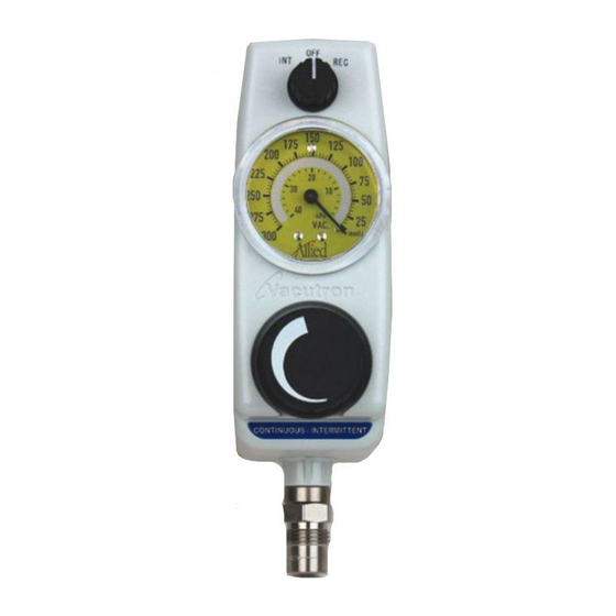
Allied Healthcare VACUTRON INTERMITTENT Kullanım ve Bakım Kılavuzu - Sayfa 7
Tıbbi Ekipman Allied Healthcare VACUTRON INTERMITTENT için çevrimiçi göz atın veya pdf Kullanım ve Bakım Kılavuzu indirin. Allied Healthcare VACUTRON INTERMITTENT 16 sayfaları. Vacuum regulators for continuous or intermittent drainage

4.0
OPERATING PROCEDURE:
After assembling the suction system, a simple adjustment and test is required as follows:
4.1
Continuous Mode:
Turn the mode switch to REG.
Occlude the hose connected to the patient connection of the collection bottle.
Wait for the vacuum reading on the gauge to rise and stabilize, then adjust the large knob to the
maximum desired level.
Remove the occlusion.
4.2
Intermittent Mode:
Turn the mode switch to INT.
Occlude the hose connected to the patient connection of the collection bottle.
Wait for the unit to cycle ON.
During the ON cycle adjust the vacuum level to the maximum desired level. Allow the vacuum level as
indicated on the gauge to rise and stabilize prior to any adjustments.
Remove the occlusion.
5.0
TROUBLESHOOTING GUIDE:
CAUTION
PROBLEMS
1.
Unit fails to draw vacuum
in all modes
2.
Erratic or low suction
3.
Erratic vacuum gauge
reading
Vacuum gauge won't zero
4.
5.
Vacuum reading too high
on gauge per regulator
specifications
6.
Unit will not shut off in
the "OFF" position.
7.
Source/Patient connection
loose
8.
Unit fails to cycle
properly in INT mode
FOLLOWING ANY REPAIR, MAINTENANCE, AND/OR PART REPLACEMENT,
VERIFY THAT THE UNIT PERFORMS IN ACCORDANCE WITH SECTION 2.0.
PROBABLE
CAUSE
a.
Aspirant drawn into unit
b.
No vacuum supply
c.
Loose or incorrect set-up
d.
Clogged filters
e.
Selector switch not fully engaged
a.
Low vacuum supply
b.
Aspirant in unit
c.
Loose or faulty connection
d.
Worn or obstructed regulator seat
e.
Clogged filters
f.
Stuck relief valve
a.
Low vacuum supply
b.
Worn or obstructed regulator seat
c.
Gauge mechanism damaged
a.
Gauge mechanism damaged
b.
Pointer bent
a.
Stuck relief valve
b.
Damaged gauge
c.
Damaged regulator
a.
Damaged switch o-rings
b.
Selector switch not completely in
"OFF" position
a.
Loose or damaged in handling
a.
INT mode not selected
b.
No source vacuum
c.
Timing circuit adjusted incorrectly
d.
Damaged mode switch o-rings
e.
Clogged back plate filters
f.
Damaged timing assembly
REMEDY
Flush unit
Check hospital vacuum level
Set-up unit
Replace filters
Move switch fully to mode detent
position
Check hospital vacuum level
Flush unit
Set-up unit
Clean or replace regulator
Replace filters
Replace relief valve
Check hospital vacuum level
Clean or replace regulator
Replace gauge
Replace gauge
Replace gauge
Replace relief valve
Replace gauge
Replace regulator
Replace o-rings
Turn knob to fully "OFF"
position
Remove, rewrap threads with
TFE tape, and set up unit
Turn selector knob to INT
Attach unit to hospital vacuum
Adjust timing controls
Replace o-rings
Replace filters
Consult factory for service
7
SEE
SECTION
6.6
+
3.0
6.7
+
+
6.6
3.0
6.4
6.7
6.3
+
6.4
6.5
6.5
6.5
6.3
6.5
6.4
6.2
+
3.0
+
+
6.7
6.2
6.7
+
