CPE C Series Kullanım Kılavuzu - Sayfa 13
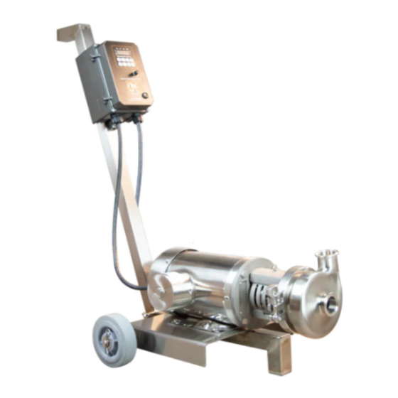
Su Pompası CPE C Series için çevrimiçi göz atın veya pdf Kullanım Kılavuzu indirin. CPE C Series 18 sayfaları. Portable pump
Ayrıca CPE C Series için: Manuel (19 sayfalar)

SETTING THE DRIVE COLLAR BY MEASUREMENT
(NOT APPLICABLE TO THE C100 MODEL
1. Install the backplate, gasket and casing.
2. Install and tighten casing clamp
3. At a location behind the backplate scribe a mark on the shaft.
See Figure 2 or 3.
4. Remove casing clamp, casing and backplate.
5. Slide the drive collar onto the shaft.
6. Locate drive collar in relation to the scribe mark as shown
in dimension A and secure to the shaft with the set screws.
Drive collar location is critical.
7. Install the seal spring, seal cups, seal o-ring and carbon onto the shaft.
SETTING THE DRIVE COLLAR BY POSITION
1. Assemble the spring, seal cup, o-ring seal, and carbon seal onto the drive
collar. Care must be taken so that the spring does not rest on the tab that is
bent back. A portion of the spring is offset to provide clearance for this tab.
Care must be taken to ensure that pins on drive collar is in line with slot on cup.
2. Install as a unit on the shaft.
3. Install the backplate and casing.
4. Install and tighten the casing clamp.
5. Slide the drive collar and seal assembly toward the backplate until the
nose of the drive collar pushes the o-ring and carbon seal tight against the backplate
6. Slide the drive collar away from the backplate 1/32" (.79mm) and secure the drive
collar in this location with the set screws
Note: Extra care should be taken when assembling "C" series pumps with type DG or FG seals. Incorrect stub shaft
settings will allow the impeller hub to contact the inboard face of the stationary seal seat. Interference of impeller hub
and seal seat face will cause wear of impeller hub and damage the inboard or secondary seal face of the clamped-in-
seat. Visual inspection is recommended after installation of the impeller, and before instalation of casing, to ensure
clearance between the impeller hub and seal face. If no clearance is visible, the pump should be dissaembled and stub
shaft moved forward, to provide at least 1/32" (.79mm) clearance between the impeller hub and seal seat face. Reset
seal drive collar if necessary.
7. When the drive collar is properly positioned and seal components are properly installed, the pump shaft should
rotate freely by hand. If excessive effort is required to rotate the shaft, check to be sure that all components are
properly installed and the drive collar is properly positioned.
MAINTENANCE
)
cpesystems.com
1-800-668-2268
Page 11
