Avsl Adastra UA Series Kullanıcı Kılavuzu - Sayfa 4
Amplifikatör Avsl Adastra UA Series için çevrimiçi göz atın veya pdf Kullanıcı Kılavuzu indirin. Avsl Adastra UA Series 7 sayfaları. Compact 100v mixer-amplifiers

Connection and setup
Set the rear power switch (11) to the "off" position and connect the rear IEC inlet (10) to the mains using the
supplied mains lead (or an equivalent approved type). Check that the supply voltage is 170-264Vac 50Hz.
A pair of screw terminals is provided on the right side of the rear panel for connection to an alarm
system if required (20). This connection will mute all channels except CH.1 (for alerts) when 24V is
present across the terminals. (24V is a standard trigger voltage from most fire and security panels)
Note: Screw terminal blocks can be unplugged from the panel for convenience during connection.
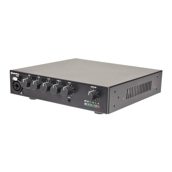
If using a main microphone for paging or announcements, connect this to the CH.1 input on the front panel
(7) via either XLR or 6.3mm jack. This may also be a line level (such as CD or mp3) input if required.
Alternatively, the CH.1 mic or line source can be connected on the rear panel via a screw terminal
input (19), which is labelled "+ / - / G".
For Unbalanced connection, connect the signal (core) wire to "+" and connect the Ground (braid) to "- and G".
For Balanced connection, there will be 2 core wires. Connect the hot (usually red) wire to "+" and the cold
(white, black or blue) wire to "-". Then connect the Ground (braid) separately to "G".
CH.1 has a bank of 3 DIP switches dedicated to it on the rear panel (16) above the terminals.
The right side DIP switch allows the VOX function to be switched on or off.
When this function is switched on, the input to CH.1 will override the other inputs, causing the
volume of any of the other 3 channels to be suppressed when any sound is present on CH.1
When CH.1 is silent, the other 3 channels return to full output volume automatically.
This function is useful for "auto-ducking" background music when making announcements.
The centre of the 3 DIP switches selects between MIC or LINE input. Position this switch depending upon
which input source is used, so that the correct channel input level is set for the input type.
The left side DIP switch is labelled "PHANTOM" and switches 24Vdc phantom power to the CH.1 front XLR
input for use with paging or condenser microphones that require phantom power.
CH.2 and CH.3 can also accept either microphone or line input, via either 6.3mm jack or screw terminal inputs
on the rear panel (14, 15)
The screw terminals for CH.2 and CH.3 are connected in the same way as described above for CH.1
For 6.3mm jack, connection can be Unbalanced (Tip +, Sleeve -/GND) or Balanced (Tip +, Ring -, Sleeve GND)
There are a pair of DIP switches (18) for CH.2 and CH.3 to select MIC or LINE, depending upon the
input type. Note: No phantom power or vox override are available on these inputs.
CH.4 is an input for Line level only and is connected via a pair of RCA sockets (13)
Connect the Left and Right output from a CD, mp3, DAB/FM tuner, message machine or other line
level source to these sockets using a standard twin RCA/phono lead (L+R are summed to mono).
CH.5 is an auxiliary input connected via a 3.5mm stereo jack on the front panel (8).
This is a line input and can be used for connecting a smart phone, laptop or mp3 player for audio playback.
A twin RCA line output (17) is provided for connecting the mix of all channels onto further amplifiers.
UA30, UA60, UA90 User Manual
