AVT 1815 Hızlı Kılavuz - Sayfa 2
Anahtar AVT 1815 için çevrimiçi göz atın veya pdf Hızlı Kılavuz indirin. AVT 1815 4 sayfaları. 4-channel remote switch controlled by any infrared remote control

VCC
U3
VCC
IR
OUT
GND
Figure 1. Schematic diagram
Assembly and test
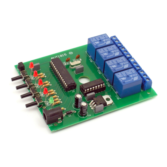
The assembly diagram is shown in Figure 2. The
assembly starts from the soldering the resistors
and other small components, and ending with
the assembly of electrolytic capacitors, relays
and screw terminals. The remote controlled
switch assembled from the tested components
does not require any adjustment and after
registering the commands sent by the IR
remote is ready for operation.
Entering the programming mode takes place
after pressing the corresponding button for
about 5 seconds. When it is done, the LED
corresponding to the programmed channel will
blink. This means that the switch is waiting to
receive and acknowledge the command from
the remote control that will be responsible for
switching the corresponding relay.
DIFFICULTY
LEVEL
2
+12V
U1
7805
D1
1
1
VI
2
1N4007
C1
3
C3
100uF
100nF
+5V
U2
R1
1
PC6(/RESET)
10k
22
GND
21
AREF
20
AVCC
C7
22pF
Q1
C4
9
PB6(XTAL1/TOSC1)
100nF
10
PB7(XTAL2/TOSC2)
16MHz
C8
22pF
8
GND
7
VCC
C2
100nF
GND
GND
GND
+5V
3
VO
GND
C6
C5
2
100nF
100uF
GND
ATMEGA8
23
S2
PC0(ADC0)
24
LED3
PC1(ADC1)
25
S3
PC2(ADC2)
26
LED4
PC3(ADC3)
27
S4
PC4(ADC4/SDA)
28
LED5
PC5(ADC5/SCL)
2
P4
PD0(RXD)
3
P3
PD1(TXD)
4
IR
PD2(INT0)
5
P2
PD3(INT1)
6
P1
PD4(XCK/T0)
11
PD5(T1)
12
PD6(AIN0)
13
PD7(AIN1)
14
PB0(ICP)
15
PB1(OC1A)
16
PB2(SS/OC1B)
17
LED1
PB3(MOSI/OC2)
18
S1
PB4(MISO)
19
LED2
PB5(SCK)
Correct reception of the remote command will
cause the LED to illuminate for a long time,
after which the LED blinking will indicate that
the switch is waiting for the confirmation of the
registered command. To do this, press the same
button again on the remote control. When the
correct command is received, the programming
procedure is completed and the switch returns
to normal operation. Entering the programming
mode is possible at any time during operation
of the device and is carried out independently
for each of the four channels.
+5V
R2
10k
+5V
S1
1
S1
S2
R6
LED1
2
LED1
1k
R7
LED2
LED2
1k
R8
LED3
LED3
1k
R9
LED4
1k
LED4
R10
LED5
1k
LED5
U4
1
16
P1
I1
O1
2
15
P2
I2
O2
P3
3
14
I3
O3
P4
4
13
I4
O4
5
12
I5
O5
6
11
I6
O6
7
10
I7
O7
8
9
GND
CD+
ULN2003AN
GND
+12V
}
+5V
+5V
+5V
R3
R4
R5
10k
10k
10k
S2
S3
S4
1
1
1
S3
S4
2
2
2
GND
+12V
REL1
1
2
OUT1
REL2
1
2
OUT2
REL3
1
2
OUT3
REL4
1
2
OUT4
