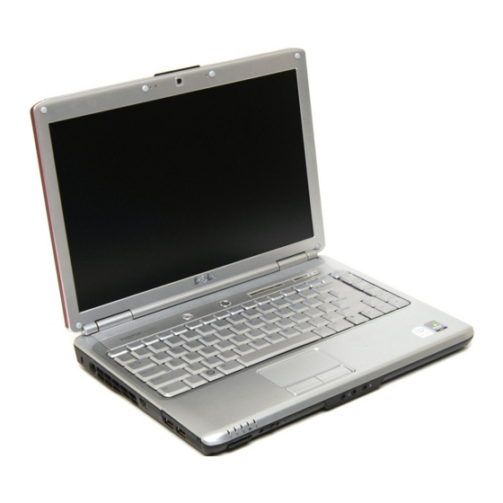
Dell Inspiron 1420 Servis Kılavuzu - Sayfa 9
Dizüstü Bilgisayar Dell Inspiron 1420 için çevrimiçi göz atın veya pdf Servis Kılavuzu indirin. Dell Inspiron 1420 46 sayfaları. Service manual
Ayrıca Dell Inspiron 1420 için: Kurulum Kılavuzu (2 sayfalar), Kurulum (2 sayfalar), Servis Kılavuzu (46 sayfalar)

Back to Contents Page
Microprocessor Module
Dell™ Inspiron™ 1420/Dell Vostro™ 1400
Service Manual
Removing the Microprocessor Module
Replacing the Microprocessor Module
Removing the Microprocessor Module
CAUTION:
Before you perform any of the procedures in this section, follow the safety instructions in the Product Information Guide.
NOTICE:
To avoid electrostatic discharge, ground yourself by using a wrist grounding strap or by periodically touching an unpainted metal
surface, such as the back panel on the computer.
NOTICE:
Handle the microprocessor module with care. Hold the microprocessor module by its edges and do not touch the processor die (the small
chip in the center of the module).
1. Follow the instructions in
Before You
2. Loosen the three captive screws securing the microprocessor module cover, then remove the cover and set it aside.
1
microprocessor module cover
NOTICE:
To ensure maximum cooling for the microprocessor, do not touch the heat transfer areas on the microprocessor thermal-cooling
assembly. Oils in your skin can reduce the heat transfer capability of the thermal pads.
3. Remove the microprocessor thermal-cooling assembly (see
NOTICE:
To avoid damaging the microprocessor, hold the screwdriver so that it is perpendicular to the microprocessor module when turning the
cam screw.
4. To loosen the ZIF-socket cam lock, use a small, flat-blade screwdriver and rotate the ZIF-socket cam screw counterclockwise until it comes to the cam
stop.
NOTE:
The ZIF-socket cam screw secures the microprocessor module to the system board.
Begin.
2
captive screw (3)
Removing the Microprocessor Thermal-Cooling
Assembly).
