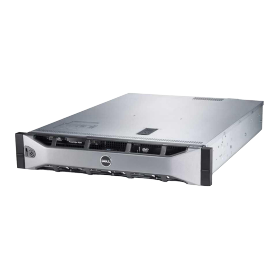
Dell PowerEdge R520 Manuel - Sayfa 3
Depolama Dell PowerEdge R520 için çevrimiçi göz atın veya pdf Manuel indirin. Dell PowerEdge R520 11 sayfaları. 2-socket, 2u rack server
Ayrıca Dell PowerEdge R520 için: Kurulum Kılavuzu (8 sayfalar), Başlangıç Kılavuzu (9 sayfalar), Portföy Kılavuzu (27 sayfalar), Teknik Kılavuz (50 sayfalar)

Cable Routing Procedures for the Dell PowerEdge R520 System
Contents
Introduction ............................................................................................................. 4
Section 1: Cabling a PowerEdge R520 system with a CMA ....................................................... 4
1.1.
Connecting the cables to the system ................................................................... 4
1.2.
Routing the power cables through the strain reliefs ................................................. 5
1.3.
Installing the CMA .......................................................................................... 5
Section 2: Replacing a hot swap power supply on a PowerEdge R520 system with a CMA ............... 8
2.1.
Replacing a hot swap power supply with a left-side mounted CMA ............................... 8
2.2.
Replacing a hot swap power supply with a right-side mounted CMA ............................. 8
Section 3: Cabling a PowerEdge R520 system on sliding rails without a CMA ............................. 10
3.1.
Routing the cables ....................................................................................... 10
3.2.
Removing the outer CMA brackets for shallow racks .............................................. 10
Section 4: Cabling a PowerEdge R520 system installed on static rails ..................................... 11
Figures
System with cables installed ............................................................................. 4
Routing power cables through the strain reliefs on hot swap power supplies .................. 5
Routing the power cable through the strain relief on a fixed power supply .................... 5
Attaching the inner CMA attachment bracket ........................................................ 6
Routing the cables through the CMA .................................................................... 6
Left-side mounted CMA installation (preferred) ...................................................... 7
Right-side mounted CMA installation (CMA shown in service position) ........................... 7
Disconnecting the CMA attachment housings ......................................................... 9
Replacing a hot swap power supply ..................................................................... 9
Figure 10. Cable routing on sliding rails without a CMA ........................................................ 10
Figure 11. Removing the outer CMA brackets for shallow racks .............................................. 11
Figure 12. Cabling a system installed in static rails ............................................................. 11
3
